 w_k_fay
This is a simplified down and dirty explanation of how to get these tubes running -no frills, cheap and cheerful, lets get it done approach. Engineers please avert your gaze "cringe warning" rank amateur content ahead.
The Russian Federation is sitting on a pile of not so old vacuum fluorescent display tubes (they made them into the 90's). This awesome tech fell out of favor in the West when LED s arrived in the seventies. However if you act now you can still scoop up a fist full of this nifty stuff for a song. If you buy them in bulk the are often cheaper than seven segment LED displays. I bought IV-3 s for about 50 cents a piece and how could you go wrong with that ? The question is what do you do once you have them ? Well... I couldn't find a simple explanation of how to use them, so they sat in their box. Looked cool as Hell though, all that retro appeal, don't you know.
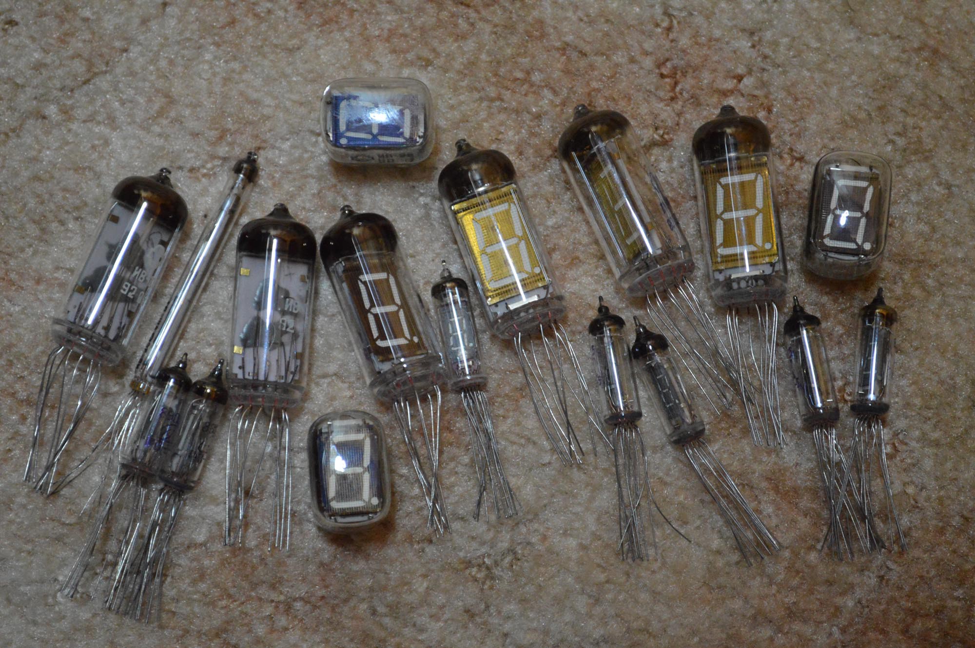
Lots of Russian VFD tubes --too many some say--
Anyway it turns out you can use them pretty much like a common cathode LED display. The idea is similar and if you have built anything with LED displays you'll quickly understand why. Let me state here that this is an article for the beginner and is not intended to describe all of the possible ways these tubes can be driven nor is it meant to enlighten the leaned. If you want esoterics try the EEVblog, that's where the cool kids hang out, but I don't hang with that gang their pool is too deep.
I will describe how these tubes work and how to test them. I will describe how to drive these tubes in a multiplexed display and in the following article I will show you how to build a frequency counter, replacing the common cathode LED s with IV-11 tubes.
For our purposes the tube consists of three components.
1 Heater or "cathode" or "filament"
2 Grid
3 Segments or "anodes"
The heater is necessary to excite the electrons and make them jump to the "anodes" which lights the segments. The grid functions as an "on off" switch for the tube when we are operating it in a multiplexed display.
Using a multi meter find the two leads with very low resistance (just a few ohms). These are the heater leads. They are not polarized. The heaters run with 1v to 1.5v for most of these Russian tubes (check your datasheet). The current draw will be 30ma to 100ma depending on the size of the tube. No current limiting resistors are needed on these tube, and they are quite tolerant to a little accidental over voltage. If you see an orange or pink glow at the base of the tube the heater voltage is defiantly too high. For your test you can power the heater with a AA battery.
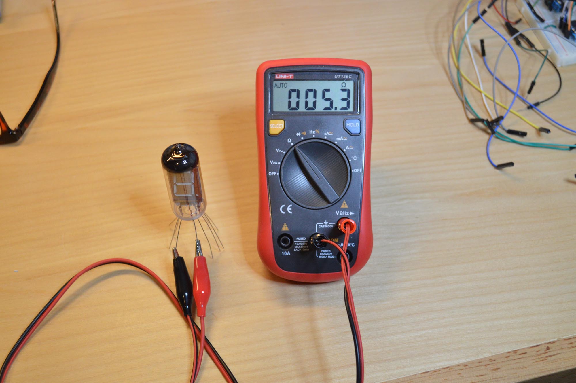
Measuring the resistance of the heater IV-11
To turn on the segments we need to supply power to the grid and the individual segments we wish to illuminate. A 9v battery is sufficient to make the segments glow. Again no current limiting resistors are needed on a VFD. Attach the 9v negative to the same pin of the heater you have attached the negative of the AA battery. Connecting the remaining leads together with the positive of the 9v will illuminate all of the segments. The grid is the lead that when disconnected turns off all of the segments. the other leads will be the anodes that illuminate the individual segments.
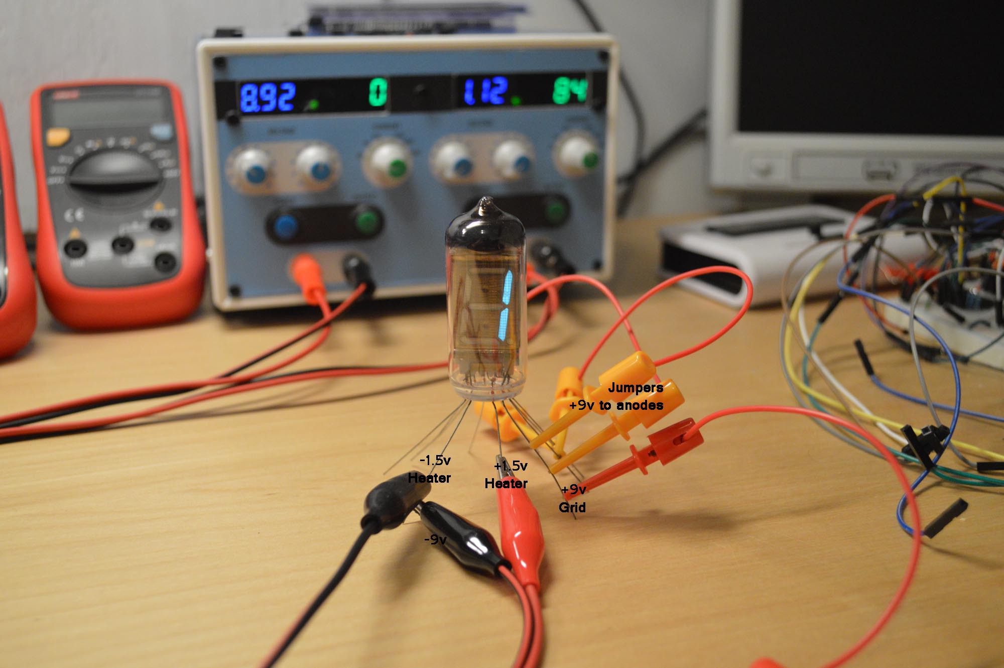
IV-11 under test
1.5v on the heater leads simulates AA battery on heater leads. Heater is drawing 84ma. 9v negative attached to the 1.5v negative on the heater. 9v positive attached to the grid. Jumper wires carry the +9v the the segments B and C. Current draw is 1ma or 2ma, too low for the power supply to register.
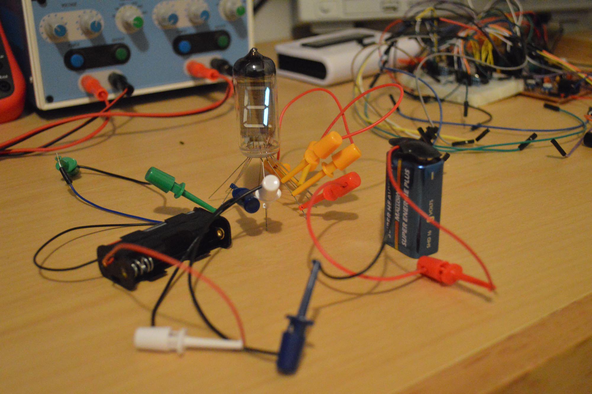
Here I am using a 9v and a AA to test the tube. Leads are connected the same as the previous photo.
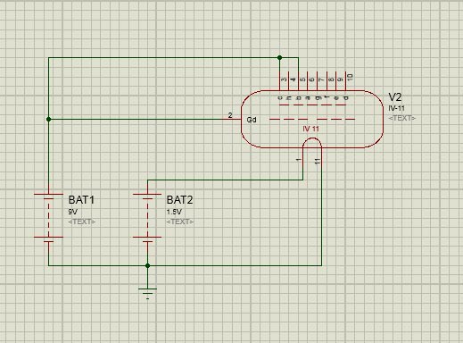
Schematic of the test
Pins 1 and 11 are the heater
Pin 2 is the grid
Pins 3 and 5 are the segments under test
The grid is shown as a dotted line between the heater (cathode) and the segments (anodes) , as it is used to control the flow of electrons between the two.
If you have ever build a project with common cathode (CC LED) displays you know that you power the segments that you want illuminated and ground the display when you want the display to illuminate. It should be easy to see from the above test that we can replace the CC LED with a VFD. We will power the segments we want illuminated and power the grid of the tube we want to illuminate. In theory that just about does it. To drive a multiplexed display some high side driver circuitry will be required. Jeelabs has a great article on high side switching https://jeelabs.org/2012/11/12/high-side-switching/ which you should read.
Here is a video of an IV-11 tube being driven by a CMOS 4026 on 13.8v. The tube is a little dim at 13.8v but shows up great on the camera. High voltage CMOS can run at high voltages and give you a brighter display. Turning up the heater voltage up a little will also brighten the tube.
The IV-11 is wired to the 4026 just like a CC LED and it runs quite respectably. You may be asking how will this work with my micro controller, Arduino or 5v TTL ? Well that is where the high side switching comes into play.
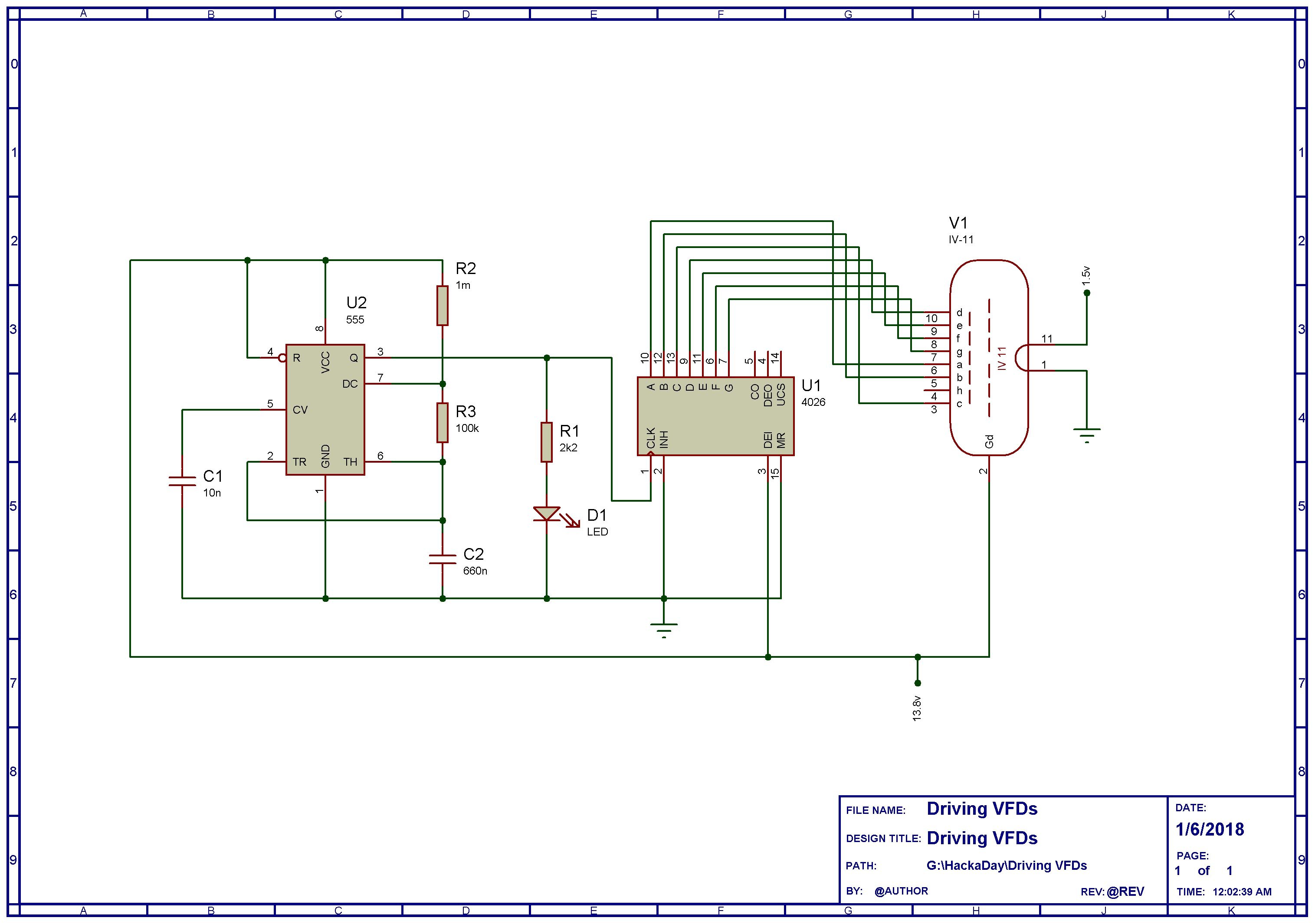
Here is a schematic of the circuit. the power pins of the 4026 are hidden but obviously go to ground and 13.8v. The grounds of the 1.5v and 13.8v supplies are tied together.
So it is possible to drive a static display (where each tube has its own driver chip and the tube is on all of the time) with common CMOS chips. The grids are permanently wired to the supply voltage of about 15v and the heaters are fed low voltage of about 1.5v. Flickering and ghosting are not concerns in this arrangement.
If you want a brighter display or you are using 5v logic then you will need a level shifting circuit to increase the 5v signal to 15v to 24v depending on how bright you want the display to be.
At this point it is worth mentioning that logic exists in three states :
1 High = Supply Voltage
2 Low = Ground
3 High Impedance = disconnected neither high or low
High Impedance (High Z) usually assumes a high state but may go low or worst of all oscillate. High Z can cause all sorts of odd behavior in your circuits. So for reliable operation we need the segment High when we want it lit and Ground when we don't. You can also see from our experiments that we need to apply power to the segment to make it light. We can't use a simple NPN transistor to control this type of load. To accomplish this we need a source driver or high side switch to turn the power on and off.
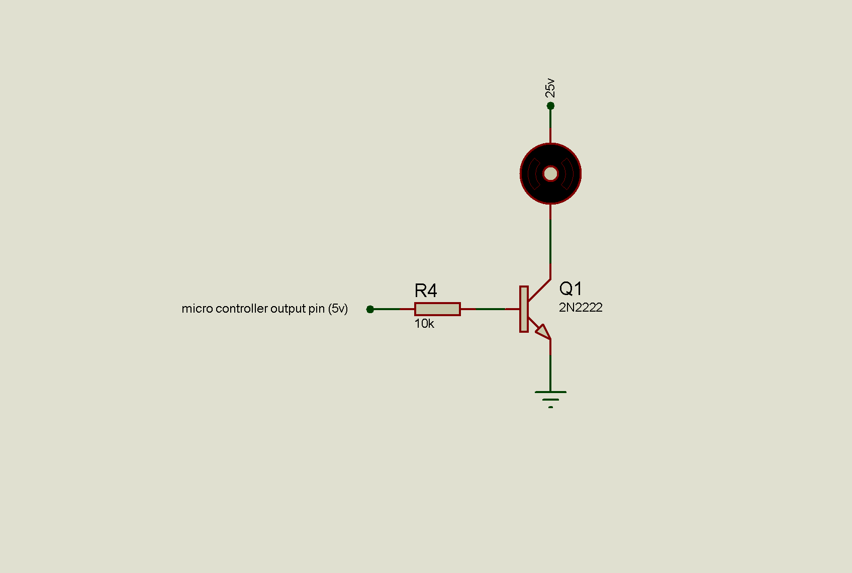
Simple NPN switch on the low side of the circuit
5v from the micro allows current to flow to ground and the load turns on. We can control loads at any current or voltage by selecting the correct NPN transistor. However with the VFD tube we are not turning the segments on by grounding then, we are turning them on by powering them.
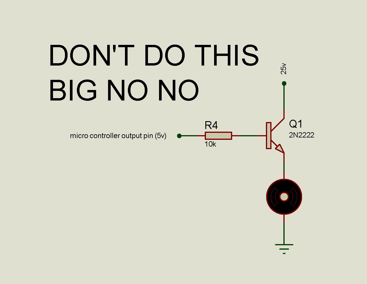
To work properly the emitter needs to be connected to ground not to the load. This arrangement won't work for most applications. Caveat :If the base to emitter voltage doesn't exceed the transistor's rating it might work in some applications, however the load should be on the high side not the transistor.
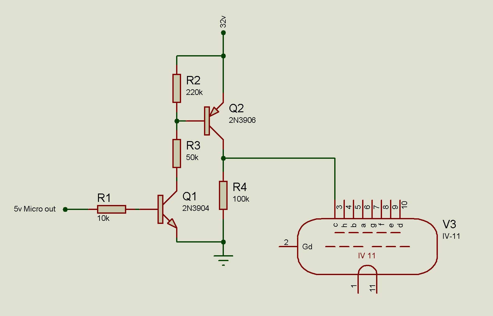
Meet the high side switch.
5v from the micro turns on Q1. R1 limits Q1 base current. Turning on Q1 creates a low voltage at the base of Q2 which turns Q2 on and sends voltage to segment C. When Q1 is off R4 acts as a pull down making the collector of Q2 ground (not High Z) and the segment is off. R2 acts as a pull up ensuring that the base of Q2 (PNP transistor) is at 32v and therefore fully off. R3 limits the base current of Q2.
We need one of these switches for each segment of each tube. That's a lot of transistors and resistors. For a multiplexed display we would only need 7 switches, one for each set of segments and one switch for each grid. One other option would be to use a source driver such as a UDN2981 for each tube.

The UDN2981 is 8 high side switches in one package. It boosts the 5v outputs of the micro or TTL to 24v. RA1 is a resistor array which provides the pull down to ground ensuring that the segment are not High z when off. You don't need an array but it sure tidies up the board layout, compared to 7 individual resistors.
Part 2 will deal with driving multiplexed displays