 Rue Mohr
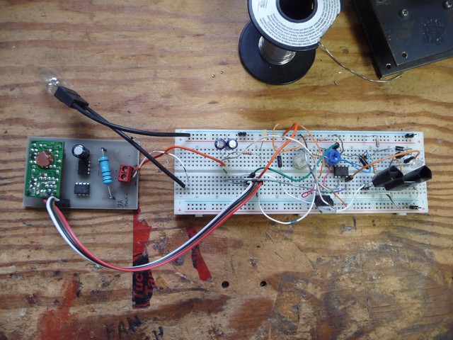
Lacking anything that can be considered real progress, I'm posting images of progress made since last log.
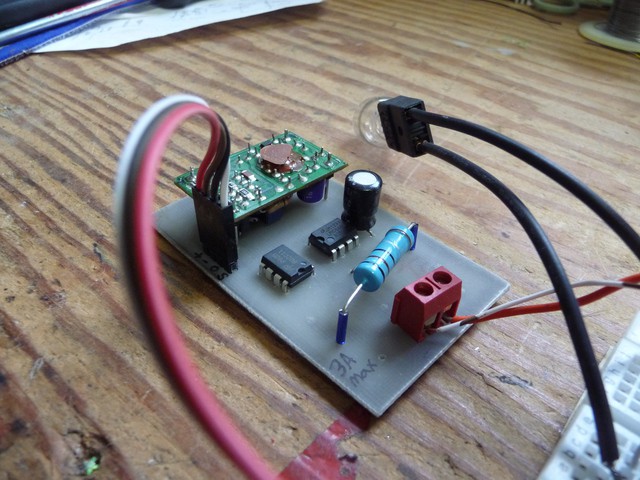
This is it wired up to my linear regulator test. Didn't entirely behave, its like its a science of soemthing :-) the piggyback board is a dc-dc isolator from thinnet ethernet cards (how many people are gonna have to look up that one!) it takes 5V in and outputs 9V, which means that the sensor can go on a power line anywhere from 0 volts up and still provide a 5V sense signal from ground.
And it works great. There are no compensation resistors because its basically a current transformer, 0-5A in causes 0-5mA out, you use a 1k shunt resistor, which you can tweek if you want to play with the output scale.
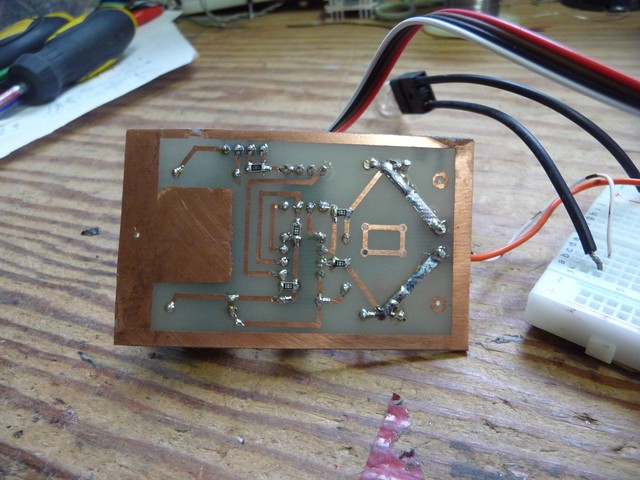
Latley I use surface mount components where its convienient, if I need to jump .4" while I go thru a resistor, I use a through hole resistor.
+, - is the power in
0,S is the zero ref and signal out
Discussions
Become a Hackaday.io Member
Create an account to leave a comment. Already have an account? Log In.