 Rue Mohr
I'm back on the project, slight distraction as I finished the digital wall clock I started 19 years ago.
I have been busy gathering up the schematics and re-glueing and testing them. things have come togethor enough for me to start building one of the 3 pcbs that will make the new regulator system.
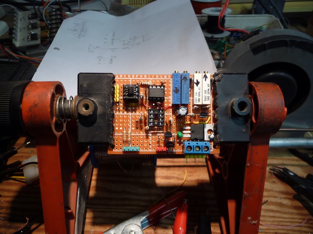
The system will be broken into 3 baords,
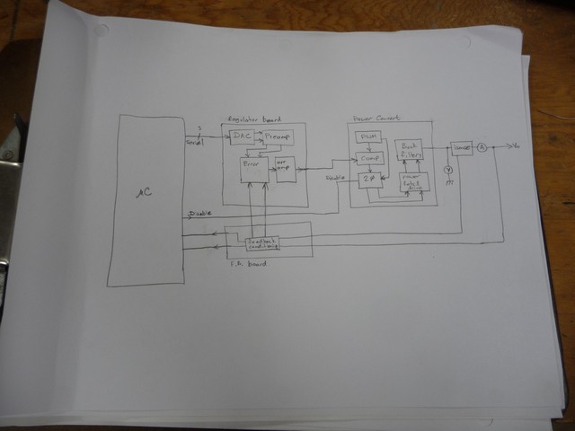
A regulator board, a power converter, and a feedback conditioner.
Schematics are as follows, some testing still needs to be done. Thanks for all the people who have helped sofar and all the peoples work that I'v stolen to get this far.
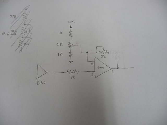
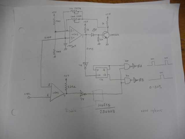
The DAC outputs 1.25-3.75V, so this expands it to 0-5V which I was trying to avoid, but made more of a mess. MCP6002 amp, 5V supply.
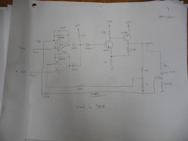
Error amplifer, this will take the voltage and current feedback, and work out what the drive signal needs to be to the power amp. The two dividers on the right were just for testing functionality.
PWM genorator, 250Khz, 2 phase. Splitting the pwm into two phases that max 50% duty means I can use a capacitor for level shifting. I'm going to insert a gate for the microprocessor to disable the outputs till everything is ready during startup.
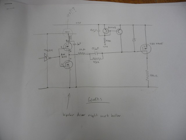
Fet driver, today I was looking at changing this to drive the fets at 12V, it would reduce the on resistance loss from 1W to 0.5W, but, it makes life really hard, so I'm going to stay with the 5V drive.
250Khz is really hard to work with, you have to pick parts carefully to get a fast enough responce.
Note the 0.1uF level shifting capacitor.
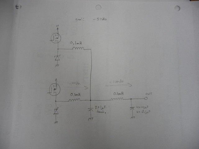
Output filter, from what I can work out, I need -57db this gives me -140db in 2 stages, the idea is that the first stage components wont be stressed (large 1uF caps) and the reduced ripple to the second stage will lower the ESR evils that usually cause those caps to fail.
Thats all, I'm gonna be testing and soldering for a while.
Why does it have to be so hard to make a variable current regulated, variable voltage supply that can go down to 0V and take up to 5A?
Discussions
Become a Hackaday.io Member
Create an account to leave a comment. Already have an account? Log In.