Ok, so the proof of concept I worked on back in October looked awesome, but it couldn't really move on its own… and there were a couple of reasons why:
- I had mounted standard servos on the drive shaft instead of the continuous rotation type. I found out you need more than a breadth of 180 degrees to make a rack and pinion move far enough to do anything useful!
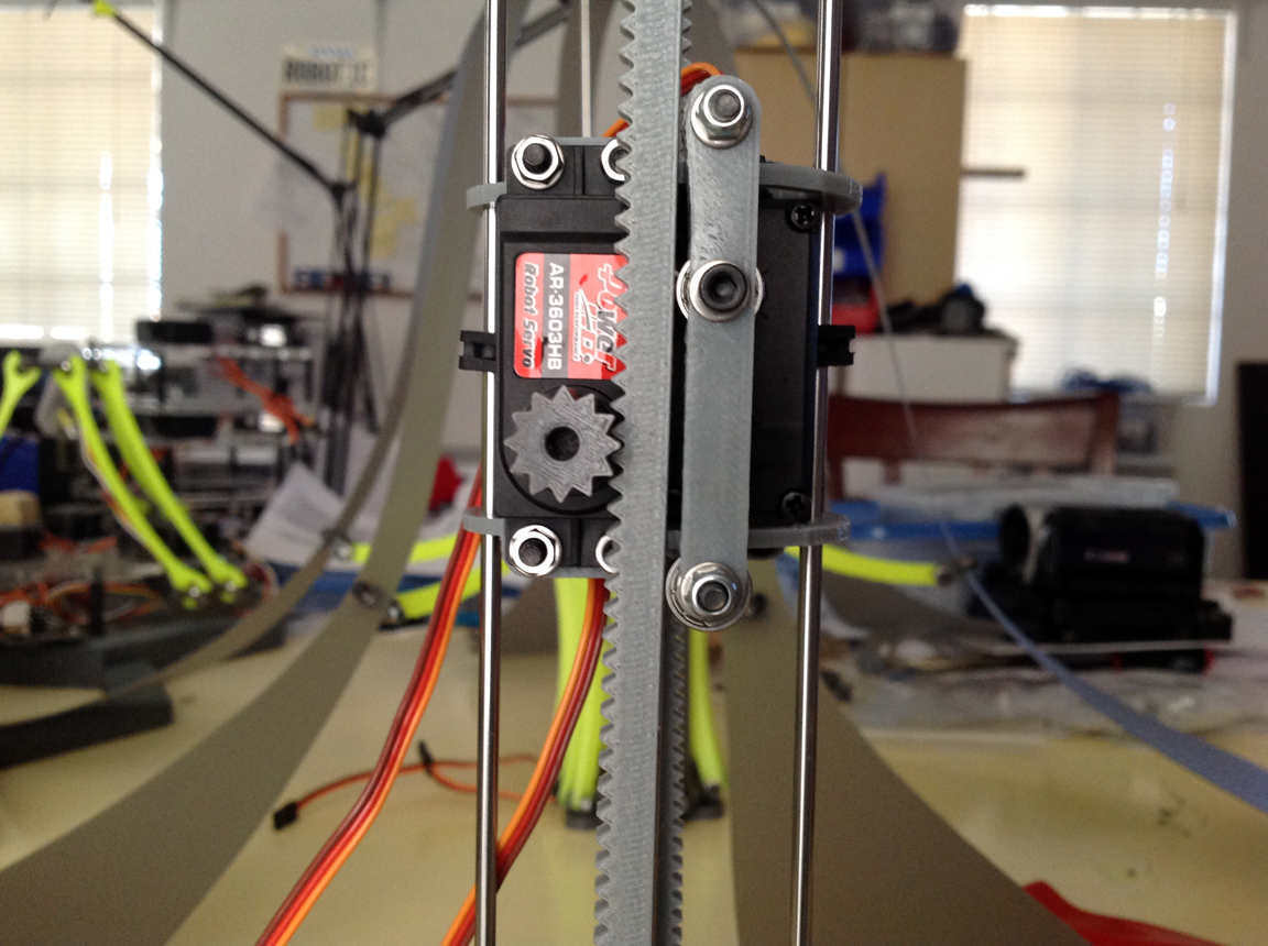
- Also, my drive shaft needed some roller bearings to tension the rack down onto the pinion in order to stop all the slippage.
Since both of these things involve the mount of the motors specifically, I took the time to completely redesign that whole part to be more solid in general… after all, it is the very core of the robot- therefore the most important part! Tighter tolerances = happy jelly.
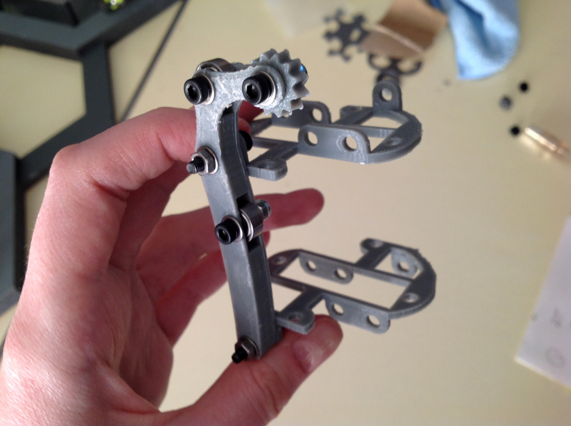
So what I ended up making was a set of brackets that both servo motors mount to… the roller bearing tensioner is a separate piece that screws into both, bridging the two and making it one solid piece:
The extra gear bit (that kinda looks like a spur in the picture above) was added to help keep the rack in alignment, but it ended up causing more problems than solving them… so I removed it. The final working rendition had a roller bearing slightly above and below the pinion itself… instead of one directly on top of it:
After these changes were made I hooked one of the new motors up to an arduino to test whether or not the thing moved… which it didn't. =[ BUT- it wasn't because of the improvements I had just made. I now had a new problem to solve.
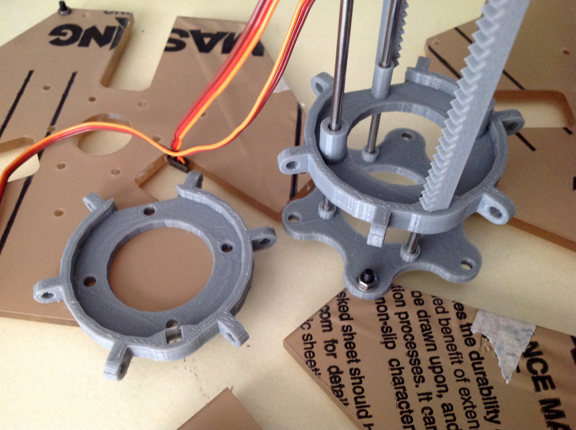
SO- the bit that is actually supposed to be moving is a sort of vertebrae or disk that slides up and down on the metal rails which the stationary servos are mounted to. One of these disks is attached to the end of each rack, but only on one side. As this goes…. when the rack moves, it tips the disk slightly at an angle… which causes it to bind on the rail rather than slide up and down it at an ideal 90 degree angle. Eh.
The solution apparently was to add some linear bearings… which I didn't have on hand- so I faked it and just added some cylindrical tubes to the part in CAD and reprinted them. This actually worked extremely well. Not as well as linear bearings, but it did get the thing working at last:
Accept… a third problem appeared at this point. Now that the properly tensioned rack and pinion was actuating the properly guided disks up and down the rails… there was really no quick way to calibrate the motors back to center every time I unplugged the power. Eh. Since these are continuous rotation motors, there is no center… so I had to manually pluck the pinion off and guide the rack back down by hand...
Which sucked. So… it was time to graduate from my uber basic sweep code to something with feedback. I wired up four buttons on my breadboard and Mark helped me write some code in Arduino so that each of the two servos had a switch for up and down. Now I have absolute control over the range of the motors!
So, the new drive shaft more or less works mechanically, which is swell. The next phase of development will include adding limit switches and a way for the jelly to zero itself out when it needs to… as well as some motor choreography so it actually jellies like a jelly is supposed to.
 Sarah Petkus


Discussions
Become a Hackaday.io Member
Create an account to leave a comment. Already have an account? Log In.