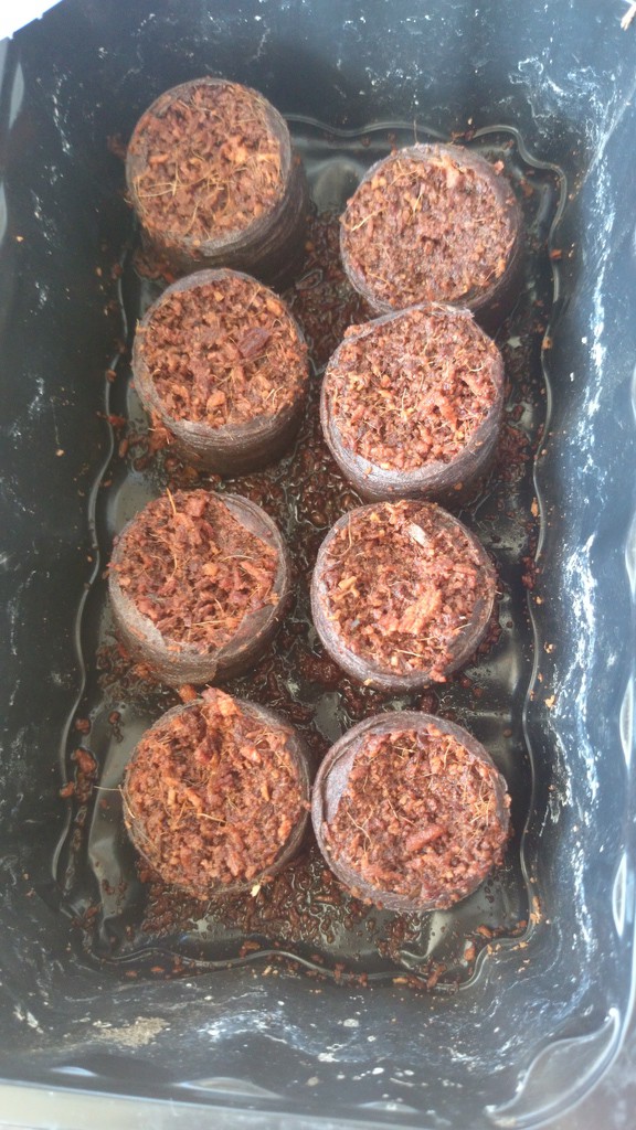
• Goodbye MSP430, Hello Arduino Clone

    Michael Haas04/17/2015 at 08:31 0 comments

    Inspired by @Joey Pongallo, I started researching pre-made relay boards instead of creating my own MOSFET-based switches. It turns out that most of these boards are made for the Arduino eco system and thus require 5V levels to switch. Some people report that their relay boards work with 3.3V logic levels, but that typically requires a separate 5V supply for the relay coils. Even then, the logic levels may be too low to drive the switching transistor to saturation. This results in a very hot transistor.

    During my research, I stumbled upon cheap Arduino clones. These boards provide 5V logic levels and the entire Arduino eco system is built around them, except for some oddball Arduinos running on 3.3V.

    I've ordered an Arduino Nano V3 clone and a 4-relay module for 13€ total including shipping. This is a much better option than spending another several hours designing and soldering the MOSFET-based switch.

    As a plus, the board can run on supply voltages up to 20V as it has a built-in voltage regulator. I could - theoretically - run the relay coils off that regulator. I will have to see about that once the board arrives and I can determine the particular type of regulator used. I would have preferred a 12V relay, but these are quite rare and also more expensive.

    If the built-in regulator can't supply enough current (70mA per coil), I still have my LM2596 based converter.


  • Unbreaking the CWX15Q CR-02 Valve

    Michael Haas04/14/2015 at 12:31 0 comments

    For some reason, my valve never worked. I disassembled it and found it would only close, but not open anymore. I found a blown trace on the PCB which I repaired, but it's still short-circuited somewhere. I believe either the reverse-voltage protection diode or the relay coil are blown and now permanently conducting. Both are easy fixes, but still very annoying.

    The CR-02 valve is actually nicely built and probably good value for your money. The PCB is sufficiently well made and the gear box looks solid. Of course, some gears are plastic although it's advertised as a brass gear box. I just wish they had added a proper fuse to the PCB instead of just letting some traces burn out.

    Edit: I just did some further test and it is indeed the diode that's burnt out and now conducts in both directions. I know that diodes are used in this way to protect against wrong polarity. In this case, all current flows through the diode and back to the battery. The key ingredient here is a fuse which prevents further damage to the circuit. The manufacturer didn't include that fuse, so the PCB trace blew up. I'm reasonably sure I did not reverse the polarity, but you can never know afterwards. It's also possible that the diode is simply supposed to act as a suppressor diode for the motor.

    Edit2: It's likely a suppressor diode for the relay coil.

    Anyways, I have (badly) drawn up a schematic which will hopefully help other netizens.

    The blue (CLOSE) wire is connected to the NC pin of the relay. This is kind of the default action for the valve. The red wire (OPEN) fires up the relay coil which changes the turn direction of the motor. There are two end switches (green wires and red wires) which disconnect GND once the respective end range of motion has been reached. These switches are conductive by default and turn off the motor when press.

    For your amusement, here is the burnt out trace:

    More Pictures

  • Some Changes

    Michael Haas04/07/2015 at 12:18 0 comments

    Spring is coming and the seeds are planted. I've made some changes to the project. Mainly, the MMM is now powered by a 12V lead-acid battery as that's the voltage required by the motorized ball valve. At 7.2Ah, the battery likely is large enough to last all of summer. I have yet to do the math on that. I choose the battery size mainly because it was cheap. Smaller batteries at 2Ah cost around 10€. There seems to be a sweet spot at 7Ah -- I got mine for 15€.

    I can easily charge the battery from a battery panel since it's 12V. Amazon.de lists some very affordable solar panels, e.g. 10W at 25€. Cheap chinese charging controllers like the CMP12 start at 8€so this would be an inexpensive, fun experiment.

    Unfortunately, these are cheaply made and I read somewhere that they don't even use PWM to adjust the charging voltage. For 15€, you can get better controllers like the CMTP01 or CMTP02 which -- on paper -- do the right thing. Even for those, you can find lots of complaints on your favorite search engine. The original plan was to get a solar charge controller and feed it from one of the random 19V PSUs I have lying around. Since none of the offering seemed good enough, I decided to buy a decidated lead battery charger, the AL-800. I suppose it's better to buy stuff that does one thing well instead of not doing two things at all.

    To finally make some progress, I also ordered a DC-DC buck converter based on the LM2596. These can be had for 2€ from China or, in my case, from a German (re-)seller via Amazon for 5€. Along with some fuses, diodes, opto-couplers and transistors, I should be able to prototype the interface for the ball valve soon.

  • Hooking up the Valve

    Michael Haas02/11/2015 at 09:23 0 comments


    The valve requires a two-way switch to flip from "water go" to "water stop". Additionally, I would like to turn the valve off completely to prevent battery drain. Here's the schematic again:

    I found a guide to use aTIP120 transistor to control a motor with an Arduino. Based on this guide, I added three transistors. The first transistor controls GND. This essentially dictactes whether the valve is powered at all. The second and third transistor make up the actual switch shown in the diagram above. Here's the current breadboard sketch:

    Here, the valve is represented by two DC motors because I didn't have the correct part handy. What's missing is (likely) proper protection for the transistors. I'd also like to prevent both transistors from allowing current to pass at the same time. Perhaps I will drive both second and third transistor from a single pin with a logic inverter.

    FWIW, I also added a proper Fritzing part for the ESP8266 which I found on GitHub.

  • New Parts Arrived

    Michael Haas02/10/2015 at 08:44 0 comments

    My master's thesis is finished and now I can get back to work. Two parts arrived: the ESP8266 and a motorized ball valve. The valve requires 12V, so I'll see how that goes.

  • A quick mock-up

    Michael Haas11/01/2014 at 14:07 0 comments

    I just finished a preliminary mockup of the circuit in Fritzing. A couple of things are still missing. I'm likely going to add a couple of switches (mosfets?) to turn off the servo and ESP8266 when not in use. Of course, the moisture sensor is just some random I2C part I re-used. The MSP430G2 will also go into a DIP socket. No need for the Launchpad.

    The ESP8266 is not represented correctly. I stole the idea and the wiring from http://robinsonia.com/wp/?p=378. The retro browser project seems to have an ESP8266 schematic. Maybe they're going to release that one day.

    I'll also add some connectors so I can disconnect the moisture sensor and the battery pack. Also some LEDs and test pins so I can see/check if the components are powered.

  • Voltage Regulation

    Michael Haas11/01/2014 at 12:32 0 comments

    ...or keeping the magic smoke in.

    The MSP430 runs at 1.8V-3.3V. The servo, on the other hand, requires 4.8-6V.

    I plan on using a 4 cell AA battery pack. With Eneloop batteries, this will result in 4.8V input voltage. Optionally, it should work with five cells. Higher voltage will result in more torque for the servo.

    Although the MSP430 can go as low as 1.8V, the DHT22 humidity sensor requires 3.3V-6V. I am not sure so sure about the Voltage for the Chirp moisture sensor. The chirp uses an ATTINY85 which comes in a high-voltage and a low-voltage version. In any case, given the DHT22 and the ESP8266, I will have to come up with a way to generate 3.3V for the logic. The servo will be powered directly from the battery pack.

    Several voltage regulars are available. After all, I am not the first person to connect some chips to a battery pack. How do I select the appropriate regulator? Easy, just use the first thing that's available in the Fritzing library: a 7803. Looking at the 7803 datasheet, we can see that it will deliver 3.3V just fine. It also only requires two additional capacitors, which makes it very easy to integrate. Unfortunately, the minimum required input voltage Vin is 5.8V. 4 AA cells won't cut it here.

    Another popular option is the LM317, which is an adjustable linear regulator. It also requires that Vin is 3V over Vout. Another possible problem of linear regulators is that can be very inefficient. Wikipedia says:

    Linear regulators inherently draw as much current as they supply. When this current is multiplied by the voltage difference between input and output, a significant amount of power is wasted as heat.

    The current drawn by the circuit is not very high. I assume that the ESP8266 is the biggest consumer, which, at peak times, draws up to ~300mA if my memory serves me right. So a 500mA regulator should be fine.

    A last consideration is the minimum power draw. If the circuit does not draw enough power, the voltage regulator ceases to function properly. For the LM317, the "minimum load required to maintain regulation" is 3.5mA. If I configure the MSP430 properly and disable all peripherals, I should be able to go below that. At least I hope I'll be able to maintain low power consumption in standby. I'm still wondering what happens with the regulator if current draw goes below 3.5mA. Even at 3.5mA, the batteries would only last 24 days.

    What we need is a Low Drop-Out (LDO) voltage regulator. LDO means that the regulator does not drop much voltage. Thus, Vout can be very close to Vin.

    The LD1117A is a good alternative. Depending on the current draw, the voltage drop is only 1V to 1.2V. This will work fine for the 4.8V supplied by the battery pack, even if the battery is almost discharged. It also requires two capacitors at 10µF and 100nF. I can't find the minimum power draw in the data sheet, unfortunately. The power consumed by the regulator itself, the quiescent current, is 5mA. That's a lot - but I'm running out of power regulators in Fritzing ;)

    For now, I will design the circuit around the LD1117A. I will add a diode to protect against polarity reversal and possibly a fuse.

    TI has some helpful blog posts on voltage regulators for the MSP430:

  • Too humid in here

    Michael Haas10/25/2014 at 18:38 0 comments

    I finally got the moisture sensor up and running.

    The DHT22 makes this extremely easy once it compiles. Just install the lib into energia, copy the example into a new sketch (else it won't compile) and hit upload.

  • Well, that escalated quickly...

    Michael Haas10/23/2014 at 10:05 0 comments

    I am still looking for a nice valve and an usable servo. For the valve, I went to local DIY stores and was surprised that they're so expensive. I had finally settled on a small 1/2" valve with internal female threading. I still needed some hose fittings for that which where nowhere to be found. Great.

    So it's back to eBay.. where I ended up buying an ESP8266 serial-to-wifi interface. Wait, what?

    Read more »

  • What's in a valve?

    Michael Haas10/19/2014 at 17:50 0 comments

    I'm going to need a valve to control water flow. I assume the plants will be watered once or at most twice a day if they're thirsty. I've looked around a bit and found quite some different valve implementations in the hobbyist community.

    Here are my requirements:

    • Must work in low-pressure, gravity-feed system (elevated bucket)
    • Must be cheap, uhm, affordable
    • Must not use a lot of power
    • Must not require mains voltage
    • Should default to closed as a fail-safe

    The nice folks at 43oh had some good suggestions and I found some more on instructables. Let's get started:

    Read more »