 Michael Haas
Now that you've hopefully ordered and received your chirp! sensor ;), it's time to connect it to your LaunchPad. The basic process is very simple, as the Launchpad acts the I2C master and the chirp! is an I2C slave at address 0x20. So let's look at the pins on the LaunchPad:
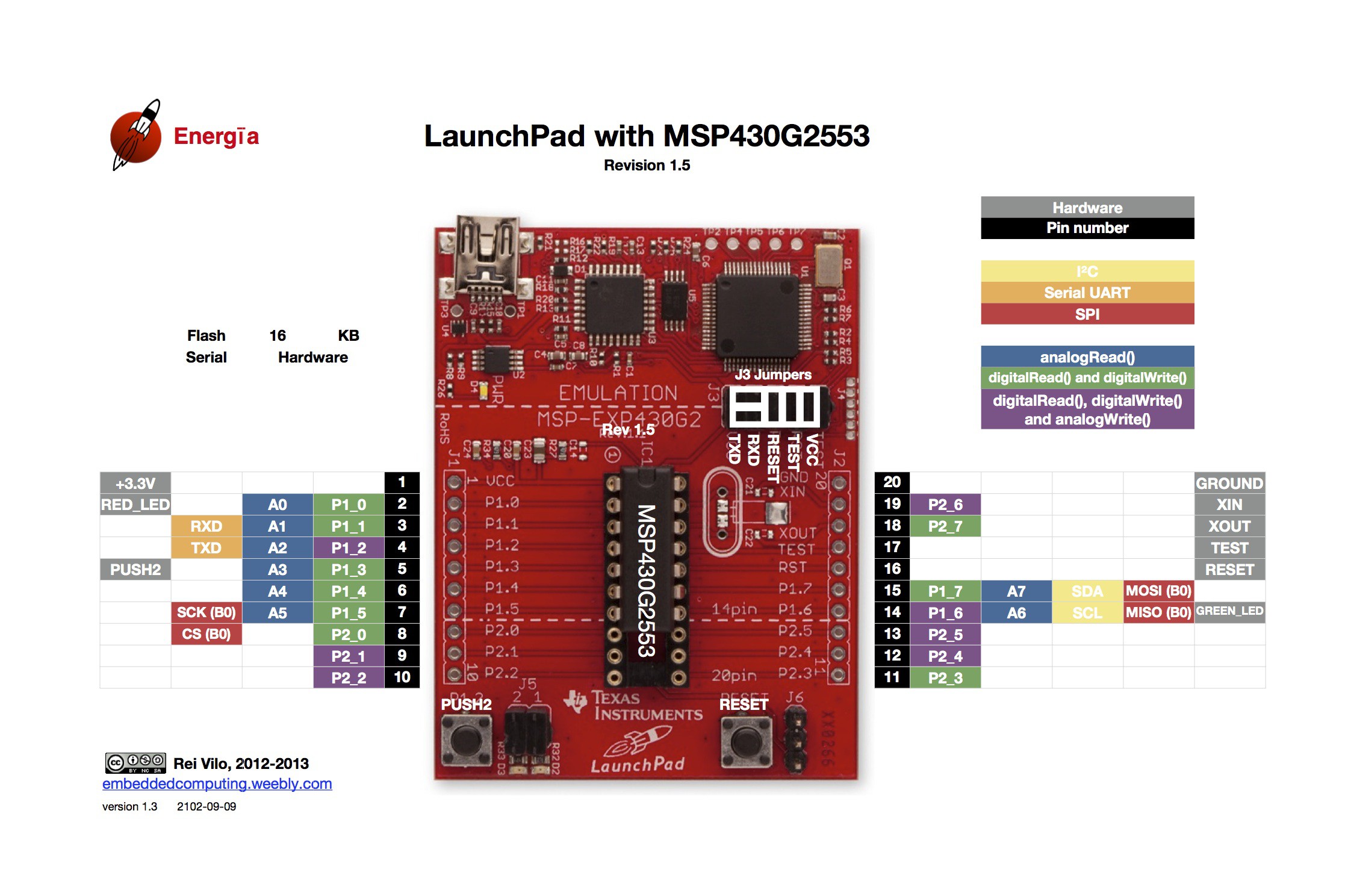
The yellow highlight marks the I2C pins SDA and SCL at P1_7 and P1_6. What threw me off here is that the pins on the chirp! also serve as an ISP header - if you want to re-program the sensor, you can do so. The pin names printed on the PCB align with the names of the SPI pins, however. So I initially connected the SPI SCK on P1_5 to the chirp!, which was completely wrong. After all, I only need SCK, SDA, VCC and GND. So here is the final mapping I derived from the chirp! documentation.
- Pin 15 (P1_7) to "pin 4 - MOSI / SDA – I2C data"
- Pin 14 (P1_6) to "pin 3 - SCK / SCL – I2C clock"
- Pin 1 (VCC) to VCC
- Pin 20 (GND) to GND
Then I fired up the latest and greatest Energia, loaded the example sketch from the chirp! documentation and got.. nothing. Tripple-check everything, still nothing. I search around and find some hints that the I2C clock needs to be reduced in some cases. Basically, an I2C slave can reduce the communication speed in what is called "I2C clock stretching" and that's broken on some devices. Fascinating stuff, go read about it.
I finally found a way to adjust the I2C clock by.. reading the documentation. If you ever despair that you can't find the right register, then be warned: some msp430s use the "USI" system for I2C, some use "USCI". Make sure to use the right registers or it won't compile...
Of course, it still didn't work. I posted over at the great 43oh.com forums where I was told I need some pull-up resistors. What? The chirp! documentation does not mention anything beyond "hook it up via I2C and use this pin mapping". The author probably assumes everyone knows about pull-up resistors, and that assumption probably is correct.
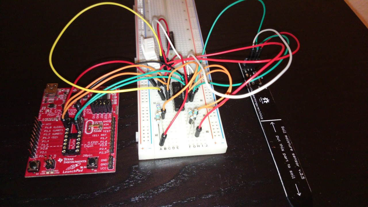
So, pull-up resistors: connect a 10k resistor to VCC and connect it between the MCU pin and the I2C slave pin. Do this for both the SDA and I2C pin. Then, the Arduino example magically starts working at the default bus speed.
The reason is that the bus should be logic high, i.e. at 3.3V, by default. That's why we connect the bus to VCC. Because we don't want to allow an unlimited current flow, we put in a 10k resistor. Otherwise, the magic smoke will escape. Now the line is logic high, but only very limited current is available. If the devices want to communicate, they pull the bus low by directing the current to GND. At least, this is my _very_ basic understanding of the issue. Remember, I'm a natural language/software guy, not an electronics engineer.
Here's the slightly overexposed result. There is a second set of resistors and some wires for the DHT22, which I will hopefully get working soon.
Discussions
Become a Hackaday.io Member
Create an account to leave a comment. Already have an account? Log In.
Hey Michael,
really nice project! I would like to give it a try but I don't get what you mean with the adjustment of the i2c clock. I read in the user guide something about clock stretching but I don't know how to implement that in the source code. What do I have to change in the source code so that it´s working?
Greetings from a not-programmer ;)
Are you sure? yes | no
Hey Eric, what micro controller are you using? Sorry for the late reply :)
By the way, the entire project is on halt as I have moved and there is only a single tomato plant left. But there is hopefully some useful stuff here.
Are you sure? yes | no
Hi Micheal,
Many thanks for your response.
The pullup resisters have been implemented. The strange thing here is we can read the temperature ( build on this probe ) smoothly but the huminity value seems not stable. These days we always received value over 900 (raw value).
I also change the sensor to Arduino again but its still not return exact value as it used to be.
The unsatability is what I encounter, so of you have any experience on this, please advise.
Thank you and have a nice weekend.
Are you sure? yes | no
Hello Michael,
Really interesting for your share.
I am now in the same situation to make Chirp wirk with my MPS430F5310.
I have work with these sensor for my Arduino and Panstamp (also AVR), everything is fine. But when switch to MSP430, there are some problems happened:
- Sometime it make the MCU halt and when reset, I can not connect to this sensor again.
- Sometime they return with raw value over 930 continuously (although with the soil-moisture of 100%, I usually get maximum of 534 raw value)
- With the same code, some of my node run well but not the same with the others.
I share my code here:
void Chirp_Init(unsigned char addr) // Init Chirp
{
UCB0CTL1 |= UCSWRST;
UCB0I2CSA = addr; // Send address
UCB0CTL1 &= ~UCSWRST;
while (UCB0STAT & UCBUSY);
UCB0CTL1 |= UCTR;
UCB0CTL1 |= UCTXSTT;
UCB0TXBUF=6; // Send 6 for reset
timeout=0;
while(!(UCB0IFG & UCTXIFG))
UCB0CTL1 |= UCTXSTP;
delayms(50);
}
unsigned int Chirp_read(unsigned char addr, unsigned char reg)
{ unsigned char i=0;
char data[2];
unsigned long Doamdat;
UCB0CTL1 |= UCSWRST;
UCB0I2CSA = addr; //Send address
UCB0CTL1 &= ~UCSWRST;
while (UCB0STAT & UCBUSY);
UCB0CTL1 |= UCTR; // Send bit for write
UCB0CTL1 |= UCTXSTT; //Send bit Start
UCB0TXBUF=reg; //Send register for read
while(!(UCB0IFG & UCTXIFG));
UCB0CTL1 |= UCTXSTP; //Send bit Stop
while(UCB0CTL1 & UCTXSTP);
delayms(80); // Delay for chirp ready
UCB0CTL1 &= ~UCTR; //Send bit for read
UCB0CTL1 |= UCTXSTT; //Send bit start
while(UCB0CTL1 & UCTXSTT);
while(!(UCB0IFG & UCRXIFG));
data[i++] = UCB0RXBUF; // Read MSB
while(!(UCB0IFG & UCRXIFG));
data[i++] = UCB0RXBUF; //Read LSB
UCB0CTL1 |= UCTXSTP; //Send bit Stop
while(UCB0CTL1 & UCTXSTP);
//P5OUT &= ~BIT2;
Doamdat=((data[0])<<8)|(data[1]); //Value = MSB<<8 + LSB
return Doamdat; //return value
}
Any of your advice is highly appreciate.
Thank you.
Tri.
Are you sure? yes | no
Hey Tri,
thanks for your comment!
I'm afraid I am not using the raw C libraries for the MSP430. I use Energia, an Arduino port. Perhaps your problems come from a wiring problem: are all calbes connected properly? Do you have the proper pull-up resistors in place?
Are you sure? yes | no