 Alex Rich
After some brainstorming with Matt Berggren (@technolomaniac) I decided to try developing a set of attachments for Stickvise that would allow it to be used for PCB milling. Some of the new features are:
1. Magnetic feet - to attach to the steel base plates used by some light duty milling machines such as the Othermill. Also turns Stickvise into an expensive refrigerator magnet!
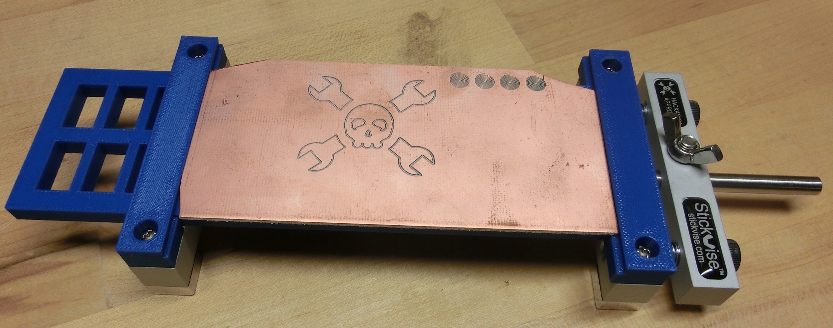
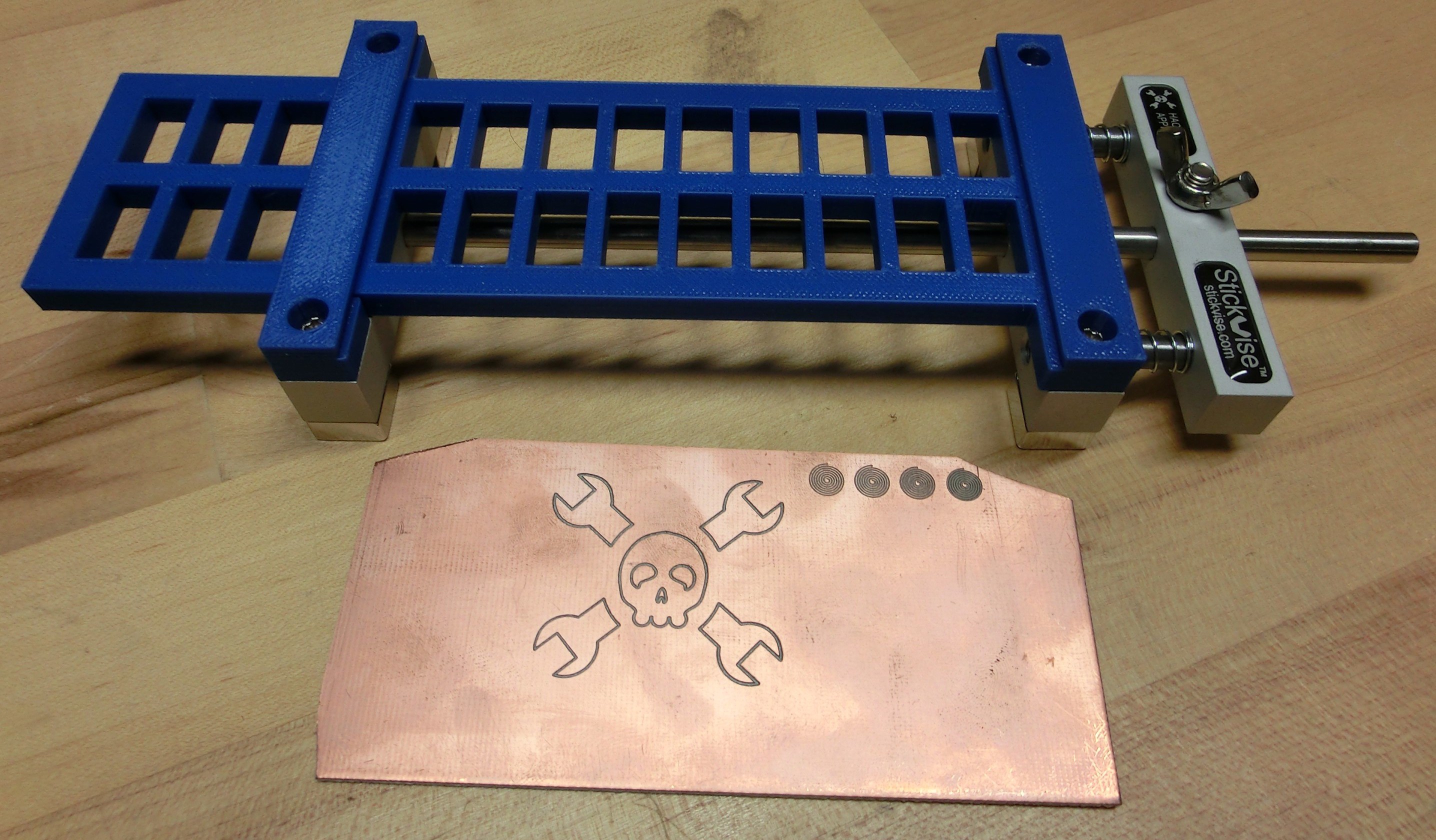
2. Special support jaws - By default, Stickvise does not support a PCB in the middle - it was designed for soldering. For milling, I designed a set of jaws that span the length of the vise to support flat stock all the way across. This prevents flexing even on very long and narrow PCBs as shown below.
Here is the prototype:
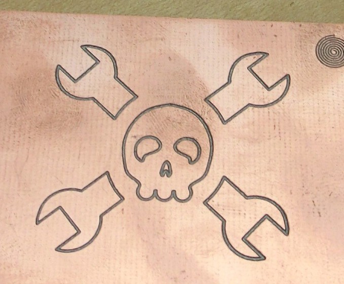
As you can see I milled a jolly wrencher without much problem. Here is a closeup:
The biggest challenge is going to be routing a board outline, the fine trace milling works great, but I did not get a chance to test full through board milling. It will be interesting to see if the magnets slip against the steel plate, or if the board slips in the vise jaws. I think it will greatly depend on how aggressive I am with the cutter, will definitely test this soon and post an update.
So far the results are promising though!
More details:
-Milled using a Tormach PCNC770, using a 1/8" carbide 60 degree v-groove cutter at .005" depth, 10,000 RPM and 10 IPM feed rate.
-Held in place using only the magnetic feet against the work table
Discussions
Become a Hackaday.io Member
Create an account to leave a comment. Already have an account? Log In.
I Should have checked my feed earlier, I was also considering a mill mounted Stickvise. I have a small conventional Proxxon MF70 which has a 7 cm wide XY table, with slots for M6 T nuts. I was thinking about a set of self registering jaws. (don't know if that's the right word, I mean self aligning to the table).
for your purpose, is there a way to cut slots in the longest axis of travel in some sort of mounting plate, and use those to align the jaws?
I like the supporting jaw, but having a printed one might give problems if you want to do a board outline. You could add a bit of expendable packing between the jaw and the board. There might even be a way to recycle left over pieces of pcb for that purpose. I don't know about the tolerances on the blanks, but they should be fairly tight, right?
Are you sure? yes | no
Yeah really the right way to do this is to have some dowel pins coming out of the bottom of the stationary jaw, then register those into reamed holes on a fixture plate on the mill or something. I was trying to come up with a solution that would not require a lot of machining - just bolt on magnetic feet and go. I need to do some more testing with the magnetic feet, they hold well but I'm not sure they will withstand routing all the way through. The PCB blanks are usually fairly accurate at .0625" thick, but I always re-calibrate z every time because the pcb milling process is so dependent on correct depth of cut.
Are you sure? yes | no