 zakqwy
... and other cool stuff @Jarod White came up with but hasn't had time to talk about. Sorry to jump the gun, friend, but feel free to comment if you have anything to add.
Revisiting the Oscilloscope
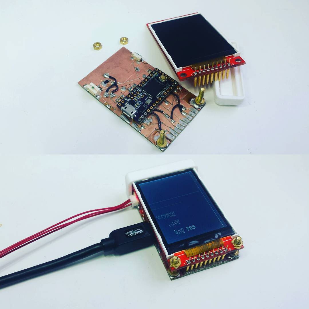
Sometime in early 2016, I created the NeuroBytes Oscilloscope, a prototype device that allowed one to view the real-time membrane potential of a connected NeuroBytes board:

I built two Oscilloscopes, one for me (below) and one for @NeuroJoe (above). The devices, based around the #Teensy 3.0 & 3.1 & 3.2 & 3.5 & 3.6 with a portrait-style 320x240 LCD, worked with ATtiny88-based NeuroBytes v0.8. The boards ran modified firmware that bitbanged UART data via one of the dendrite connections. Note the baud rate indication on the LCD in the image above; the bit-banging wasn't carefully clocked, so I tweaked the Teensy's UART speed to get good data (in this case, at 765 baud).
We didn't anticipate the reception we would get showing these devices to potential customers. At Maker Faires, on college campuses, and in high school classrooms, the consensus came in that this was our missing piece. Viewing real-time membrane potential allowed the user to fully grasp the meaning of the LED color on each NeuroBytes board. Students immediately grasped concepts like temporal and spacial summation, dendritic weighting, action potential thresholds... the list went on. The Oscilloscope had the makings of the NeuroBytes 'killer app'.
Platform Change
After NeuroBytes v0.91 (the green boards), we decided to change microcontroller platforms from the ATtiny88 to the STM32L0. Part of this was performance-driven; our decay algorithm at the time made use of 16-bit variables on an 8-bit micro, something that could cause issues with our use of pin-change interrupts if we weren't careful. And the ATtiny88 lacked three independent timer outputs, meaning the RGB LED had to be PWM'd manually. This led to all sorts of code optimization tangents that never really eliminated LED flicker and significantly limited algorithm complexity.
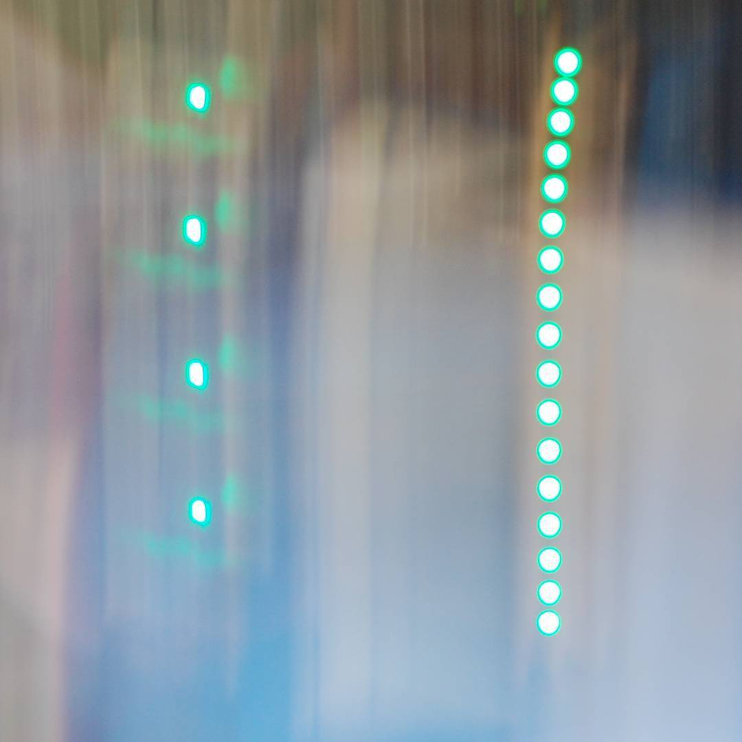
[above, swinging a long-exposure camera at NeuroBytes v0.4 (left) and v0.8 (right). Flicker got better, but 160 Hz still ain't good enough for an RGB LED running at 10% brightness.]
Mostly, the decision to switch microcontroller platforms was driven by cost. Say what you will about the Microchip acquisition of Atmel; all I know is that around that time, ATtiny88 prices doubled and suddenly the 32-bit L0 was the budget option. Goodbye avrdude, hello st-link and libopencm3.
When I designed the first NeuroBytes boards based around this new processor, I wanted to build in oscilloscope functionality from the start. I also wanted to ditch pogo connections for programming so end users could more easily reflash boards. And we wanted a dedicated and unique (i.e. not 4-pin) power connection for each board -- students were getting confused by the notion of plugging a battery pack into an axon or a dendrite ("but I thought neurons were unidirectional, why does the power connection not matter... ?"). In any case, I added on a 7-pin JST GH connector for power, programming, and a dedicated SPI port for the 'scope:
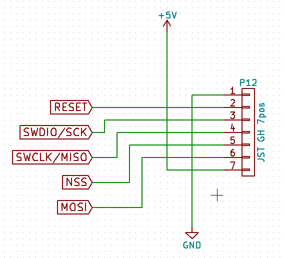 We eventually ran into issues with the 7-pin JST GH connector; the plastic webbing on the top of the connector spanned far enough that it was easy to damage. The clear answer was to ditch the SPI NSS and MOSI lines and move to a 5-pin connector.
Jarod has an idea
The new oscilloscope concept, as I planned it at least (with 4 channels), would have worked something like this:
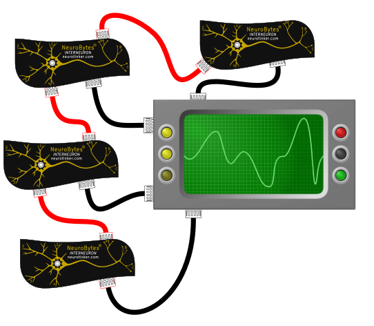 Black wires are 'scope data, red cables are NeuroBytes impulses. Problem: cables are expensive and tend to get out of control when you have a lot of them in a small space. Jarod thought we could do it like this:
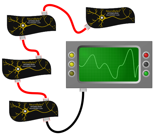 The NeuroBytes would send data along the same cables as they originally sent simple pulses to indicate action potentials. Inter-neuron communication! Data packets! Routing! Loops! Gah! I told him to prove he could get it to work, and in the meantime I kept the SPI port exposed as a backup.
 JARONET
He got it to work. I started calling the inter-neuron communication protocol JARONET, but eventually we started saying 'NeuroBytes Comms' or 'interneuronal communication protocol'. But I wanted to say 'JARONET' one last time, so.. here it is. JARONET.
We spoke with a great number of smart people about this problem and were frequently told to use a standard peripheral and an established protocol; I2C came up a lot due to its ubiquity. However, the NeuroBytes use case presents a few challenges to this plan:
- Some of our boards, such as the Interneuron, include 7 individual connections that are all intended to be used simultaneously. We'd need a microcontroller with an on-board peripheral multiplexer or one with sufficient channels to cover all dendrites and axons, or we'd need to bit-bang everything. More on that shortly.
- We simulate neurotransmitters using cables and distinguish between excitatory (red) and inhibitory (blue) connections. These cables can be wired differently, but they have to use the same connectors and don't have any active components. NeuroBytes v0.8 and v0.91 simply added a fourth signal wire to indicate inhibitory pulses; if both lines went high, the downstream NeuroBytes board knew to decrease its membrane potential. In other words: the protocol needed to handle straight-through and crossed data lines, and adapt to both cases on the fly since the network can be freely reconfigured at any time.
- Data needs to go both directions. The Oscilloscope (later the NID, or Network Interface Device) could be connected to a sensory neuron at one end of the network or an Interneuron in the middle; in both cases, the user needed to be able to get data out of any board on the network. So while the v0.4, v0.8, and v0.91 NeuroBytes were unidirectional (i.e. the dendrite pins were always configured as inputs), the new boards would need to be flexible depending on neurotransmitter cable type and location on the network.
The solution was a low-speed bit-banged communication protocol based around pin-change interrupts and multi-part variable-length messages. All of the communications bits live in the NeuroBytes_Common GitHub repo, since they're shared among all boards. Jarod has done a great job documenting the various messages so I'll reproduce his comments verbatim:
/*
    This and comm.c define all communication protocol using the NeuroBytes
    protocol specification.

    All packets are between 4 and 32 bits in length and begin with 1-bit high
    and a 3-bit message header:
    [1-bit high] [3-bit header]
    The message headers are:
    0b000  -   Unused
    0b001  -   Blink (Debug)
    0b010  -   Data to NID
    0b011  -   Downstream Ping
    0b100  -   NID Global Command
    0b101  -   NID Selected Command
    0b110  -   NID Ping
    0b111  -   Downstream Pulse
    There are three types of communication that are supported in this protocol:

    1.  Network Interface Device (NID) broadcasting to all neurons in the
        network.
        Messages are sent by NID and received by all devices on the network.
        Global Commands are processed by every device on the network.
        Selected Commands are processed only by the device with the channel
        specified by the message.

        Included message headers:
        0b001 - Blink
        0b100 - NID Global Command - Send a command to the entire network
        0b101 - NID Selected Command - Send a command to a previously selected device
        0b110 - NID Ping - Propogate ping in order to update NID route

        ####### NID Global Command ########
        NID Global Command structure:
        [1-bit high]
        [3-bit header]
        [6-bit command]             - See list of global commands below
        [More depending on command]
        Global Commands:
        0b001 - Identify. Followed with 3-bit channel
        0b010 - Version. Followed by 16-bit board id and version number. Used to blink out-of-date boards.
        0b011 - Pause.
        0b100 - Play.
        0b101 - Zero
        0b111 - Span
            *Note: 6-bits is probably excessive for global commands. Might change in the future.
        Example NID Global Command:
        Identify new neuron on channel 2.
        1           [1-bit high]
        100         [NID Global Command Header]
        000001      [Identify Command]
        010         [Channel 2]
        _______
        = 0b1100000001010

        ######## NID Selected Command ########
        NID Selected Command:
        Used to either send a command to a specific neuron (e.g. go into
        learning mode) or change the value of an operating parameter
        (e.g. set dendrite 1 to 120%)
        NID Selected Command Structure:
        [1-bit high]
        [3-bit header]      - always NID Selected Command Header (0b101)
        [3-bit channel]
        [1-bit change parameter flag]
        [4-bit command] OR [4-bit parameter ID] - depending on if [change
            paramater flag] is set
        (optional) [16-bit data]
        NOTE: Parameter IDs are board-specific (i.e. different for every board).
        They are not all fully specified yet. Currently Interneurons and
        Motor Neurons are set.
        Their values can be found in their repos (main.c).

        Example NID Selected Command:
        Set the value of dendrite 1 on an interneuron on channel 4 to 256
        1                   [1-bit high]
        101                 [NID Selected Command Header]
        100                 [Channel 4]
        1                   [Change Parameter]
        0010                [Dendrite 1] *Parameter IDs can be found in main.c for each board (NOT FINAL)
        0000001000000000    [Change to 256]
        ________________
        = 0b1101100100100000001000000000

        ######## NID Ping ########
        Functional Summary:
        NID pings are periodically sent (~200 ms) by NID to the whole network
        in order to update the shortest-route-to-NID memorized by every device.
        The NID ping packet contains a 6-bit distance field which is
        incremented by every successive neuron. The shortest route is
        determined by every neuron to be through the dendrite/axon that
        receives the NID ping with the shortest distance value. Memorized NID
        connections are lost if a NID pin is not received within
        NID_PING_TIME (~1000 ms).

        NID Ping Message Structure:
        [1-bit high]
        [3-bit header]      - always NID Ping Header (0b110)
        [6-bit distance]
        NID Ping Example Message:
        NID Ping relayed by two neurons so far
        1           [1-bit high]
        110         [NID Ping Header]
        000010      [distance = 2]
        _______
        = 0b111000010

    2. Selected neurons sending data to the NID.
        Messages are sent by identified devices and are relayed along the
        shortest path to the NID. The shortest path to the NID is maintained
        by NID pings. Messages sent from identified devices to the NID.
        Capable of sending many different types of data (16-bits) to the NID.
        Included message header:
        0b010 - Data to NID

        ######## Data to NID #######
        Data message structure:
        [1-bit high]
        [3-bit header]              - 0b010 (Data Header)
        [3-bit subheader]           - specifies type of data being transmitted
        [3-bit channel]             - specifies channel sending the data
        [1-bit fire flag]           - flag indicating the neuron fired
        [4-bit parameter id]        - (optional) further specifies the type of
            data (e.g. dendrite weighting number)
        [16-bit data]
        Subheaders:
        0b000   - membrane potential
        0b001   - board type
        0b010   - unique id
        0b011   - operating mode
        0b100   - board-specific parameter
        At this time, board-specific parameters (for Parameter ID) have not
        been fully assigned. But some values can be found in their respective
        firmware repos in main.c

        Example Data Message:
        Data message from an interneuron on channel 3 sending its membrane potential:
        0b[1][010][000][011][0][0000][0000001101011100]
        Motor neuron on channel 1 sending dendrite 1 value of 2048
        1                   [1-bit High]
        010                 [Data Header]
        100                 [board-specific parameter]
        001                 [channel 1]
        0                   [fire flag 0]
        0100                [Dendrite 1 Parameter ID]   *see motor neuron repo for Parameter IDS (NOT FINAL)
        0000100000000000    [dendrite 1 = 2048]

    3. Upstream neurons sending pulses to downstream neurons (axon -> dendrite).
        All neuron->neuron communications are maintained by the downstream
        ping which distinguishes excitatory and inhibitory connections.
        Only two messages sent in this category:
        0b1011 - Downstream ping message
        0b1111 - Downstream pulse message
*/
There are messages that establish optimal routing from each NeuroBytes board back to the NID; there are messages that identify which type of neurotransmitter cables connect boards; there are messages that simply send action potentials to downstream NeuroBytes (which in previous generations were 5V 200ms blips); there are messages that reconfigure parameters on a given board; there are membrane potential messages; and there are many more functions we have planned for the future. As of today, the protocol is extensively tested, extremely robust, and gives us a ton of bandwidth for future expansion. On an arbitrary 20-NB network, we can easily pull 20 update/second membrane potential data out four random NeuroBytes boards without any detriment to standard network functionality (i.e. normal action potentials, etc). And we've tested higher data rates and higher simultaneous channel counts without issue.
More to come.
This post is long enough so I'll dedicate a future update to NID functionality and the companion tools (Android app and Linux command line interface) that allow user interaction.
Discussions
Become a Hackaday.io Member
Create an account to leave a comment. Already have an account? Log In.