 Jarod White
I’m Jarod and I’m a physics/electrical engineering student at the University of Minnesota and am really excited to be a newly hired intern at Neurotinker! My first project here has been to revamp the 3D-printable patellar reflex model. The original principles of the model have stayed the same: 3D print a leg and thigh piece and hook them up with four NeuroBytes, two servo motors, and a button to create a neurologically accurate model of the patellar reflex! My project was to make the 3D printing and assembly process as easy as possible so that users can focus more on learning neuroscience and less on intricate 3D printing and assembly.
The patellar reflex is a great starting model for new NeuroBytes users because it uses only four NeuroBytes and demonstrates a neurological phenomena that everybody recognizes (even an engineering student with no neuroscience experience :>). Two muscles cause the leg to involuntarily kick when the patellar ligament is struck--the quadricep and the hamstring. The quadricep sits on top of the thigh and its motor neurons are told to contract and jerk the leg when the patellar sensory neurons send a signal. The hamstring sits on the bottom of the thigh and normally stays contracted to keep the leg from moving--but an inhibitory signal from the patellar ligament tells it to relax and let the quadricep do its thing.

[image by Amiya Sarkar, available on wikipedia here]
A button embedded in the leg model functions as the patellar tendon and is connected via an excitatory cable to a sensory neuron. An impulse from the button is enough to fire the sensory neuron and send an impulse through its axons. One axon is connected to the quadricep motor neuron via an excitatory cable and causes the quadricep to contract (i.e. move its servo motor) and pull the leg up. The other axon sends an inhibitory impulse to the hamstring motor neuron and goes through an interneuron on its way. Interneurons are located in the ‘processing centers’ of our body like the brain and spinal cord and routing signals through them causes a brief delay. In contrast, the signal from the patellar neuron to the quadricep motor neuron does not go through an interneuron which causes the reflex to happen more quickly and also makes it involuntary. The hamstring motor neuron relaxes (i.e. moves its servo) to allow the quadricep to move the leg in unison but doesn’t actually do any work in making the motion happen.
Building this model not only teaches students how neurons in our body function, but also shows how a simple kicking motion hides a ton of complexity in how a network of neurons, talking to each other only through brief electrical pulses, can coordinate motion.

The original patellar reflex model did this demonstration very well but was difficult to print and assemble. Printing was made difficult by the substantial amount of support structure necessary to get the thing printed which required a laborious, and sometimes painful, removal process. Assembly was difficult and mostly improvisational as the servos and button had to be mounted with tape and zip ties. The model’s support structure, which used four screws as a sort of tripod, was also finicky and unreliable.
My goal was to design a new model that could be printed without support structure and could be fully assembled easily and intuitively with only a couple parts from Home Depot or a local hardware store. Zach calls this design condition the ‘Home Depot test’ and, for this and future kits, is a very important design requirement that means users can create all sorts of cool models with NeuroBytes without having to buy costly custom-manufactured components. I also used a free CAD tool (Fusion 360) and will open source all of the design files so users can customize the model to their needs--and also contribute to a growing ecosystem of NeuroBytes models.
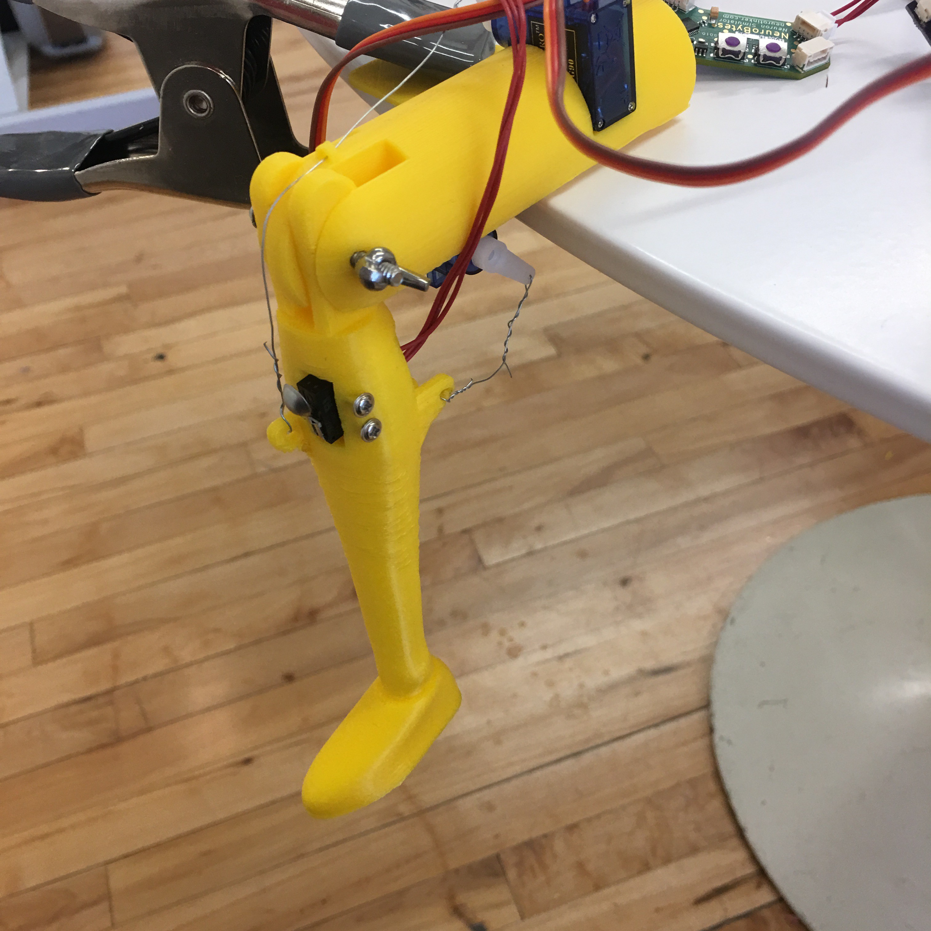
The first major change I made was to switch the anatomical skeleton leg to a cartoonish leg with a shoe. The skeleton leg had lots of small features and didn’t lay flat on the print bed which created unnecessary complications. The servo motors already come with screws that fit their mounting holes so I made the new servo housing use the screws instead of tape and zip ties. Each servo comes with two screws, but only one is necessary to mount each servo, so I used the two extra screws to mount the button inside the leg. Conveniently the servo screws fit the mounting holes on the button as well!
The new patellar reflex kit now hangs off the edge of a table and can be secured either with a clip ($0.99 at Home Depot) or with a book and something heavy. The servo motors are easily mounted in thigh insets with the supplied screws. The muscles are assembled by connecting a wire between the servos and connection holes on the leg. To mount the patellar tendon button, insert it in the form-fitted hole in the leg and secure it with the screws leftover from the servo. To finish the assembly, simply insert a 62-30 sized screw in the hole joining the knee and the thigh to act as an axle. The size of the hole can also be easily changed in Fusion 360 to fit any screw you might have lying around.
Now you can hook up some NeuroBytes in the patellar reflex configuration described above or create your own version!
Discussions
Become a Hackaday.io Member
Create an account to leave a comment. Already have an account? Log In.