 Nyles
Nyles FTF = File To Fit. Yeah, V1.0 of everything seems to have problems. :)
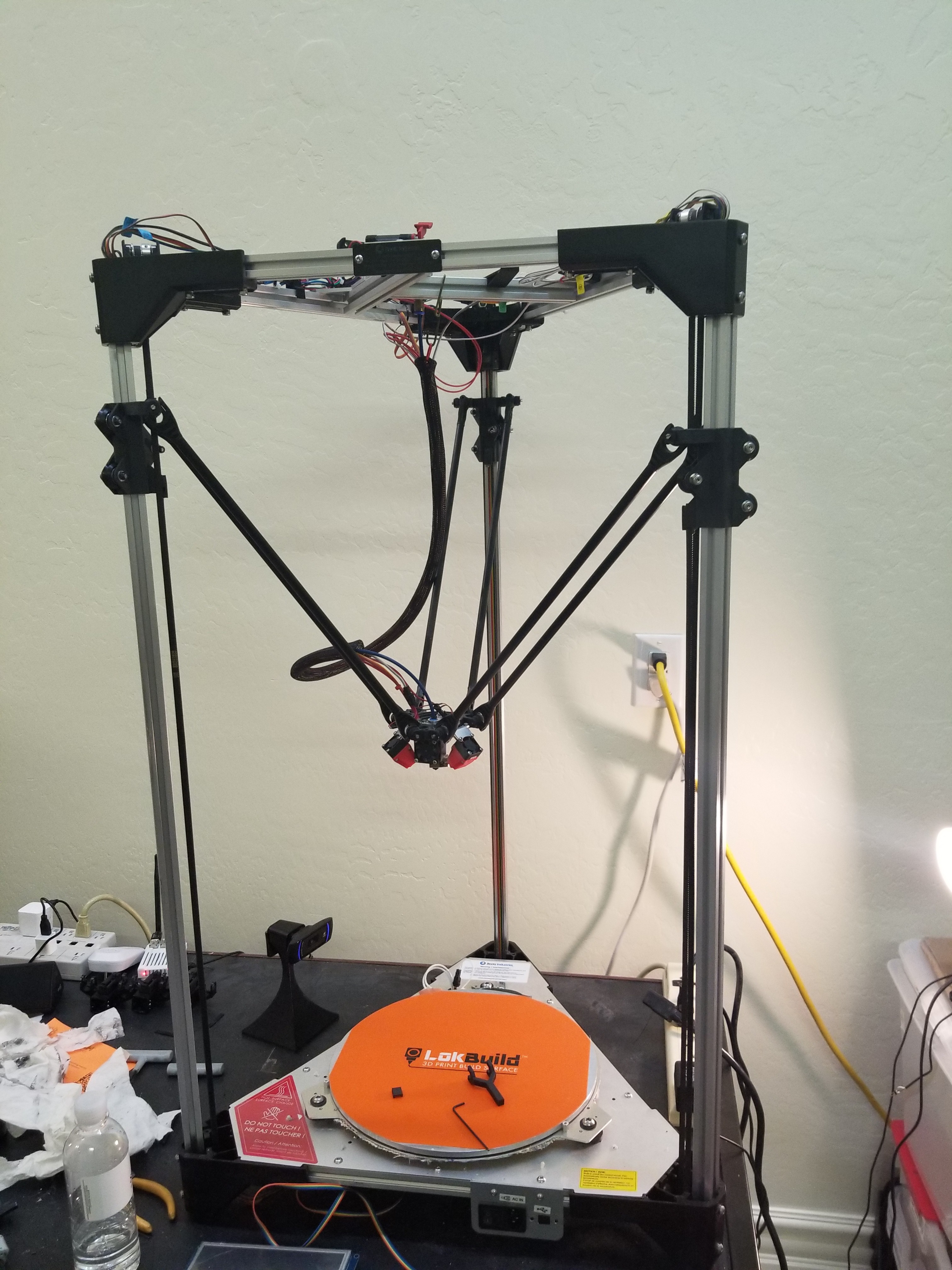
Anyway, good news. The beast is up and running with the Frankencarriage install - after extensive fiddling and cracking and patching and filing.
Here are some pics:
This is the original carriage - note the lack of wheels or anything that won't eventually wear away the plating of the aluminum rail
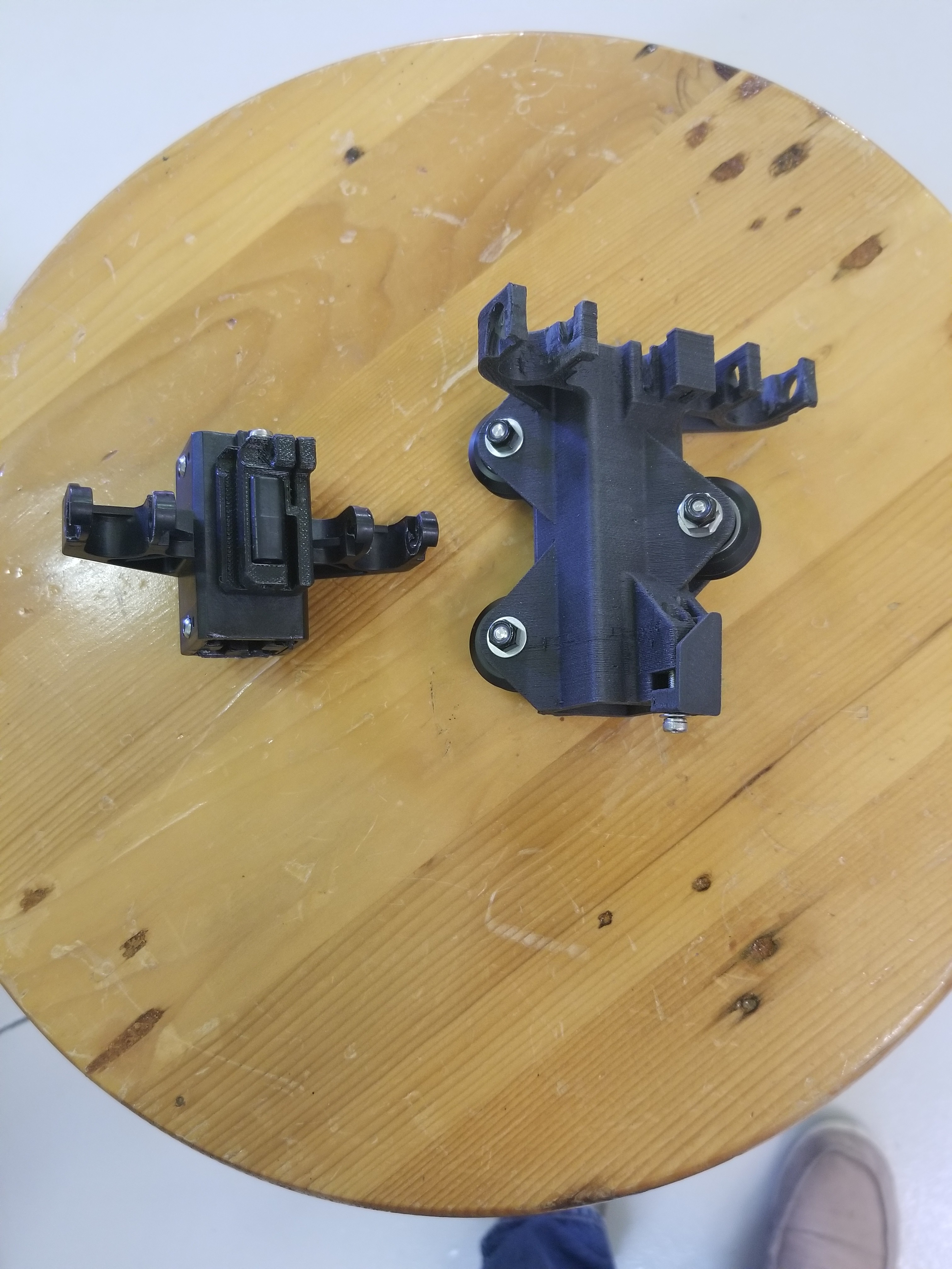
Both types of carriage... and my foot.
To change out the carriages, you have to remove the head while carefully unthreading the cables that run through the corners.
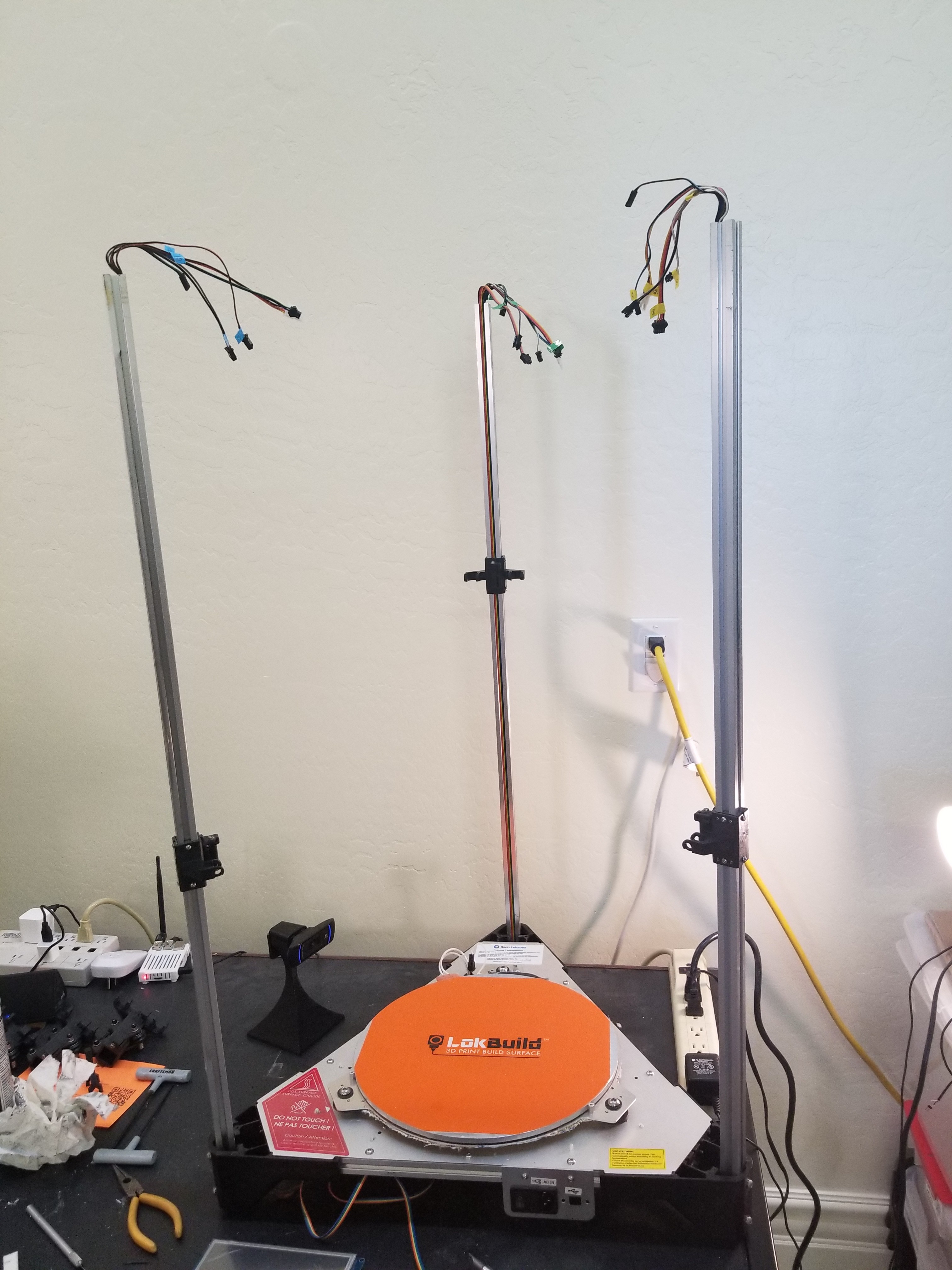
Look Ma, no head!
After this it's relatively simple to tease the cables through the carriages.
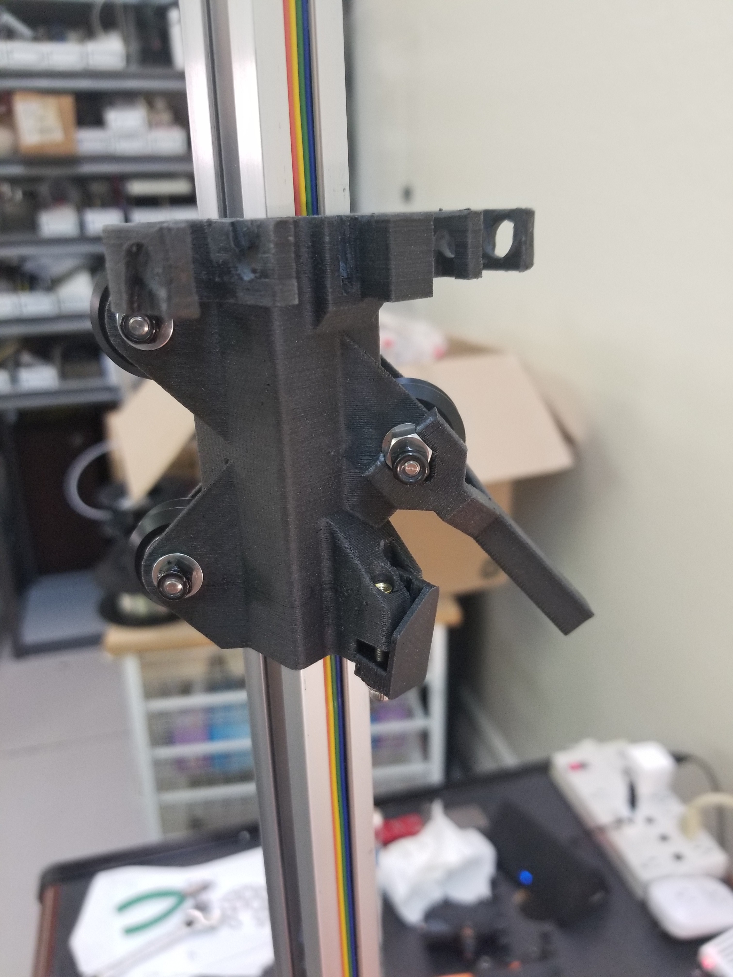
First Frankencarriage in place, with the two-headed adjustment wrench. Little did I know the fun and games to come...
They look good! At least to me; it's been a fair bit of work to get this far. Still, lurking in the shadows are a couple of problems.
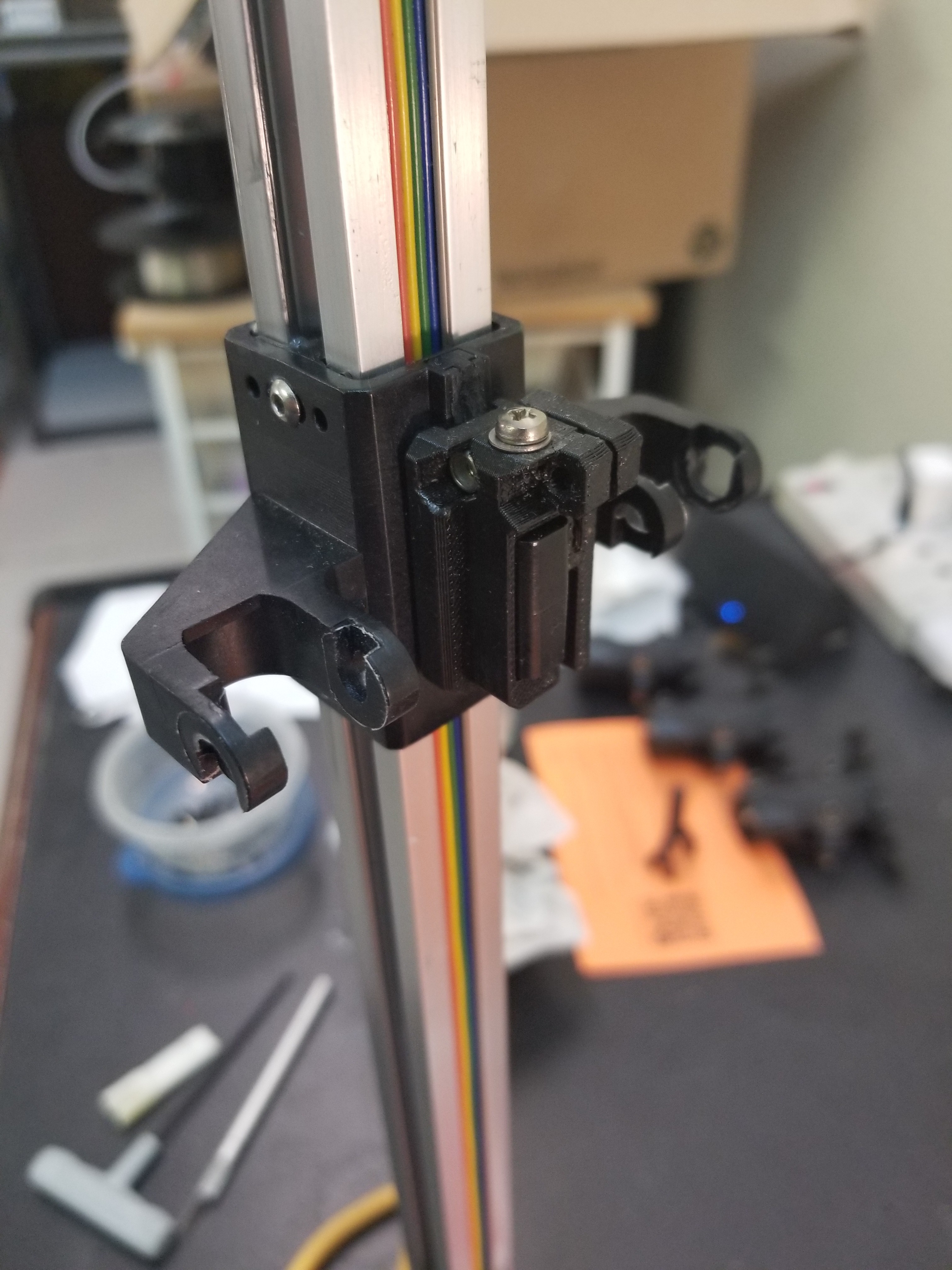
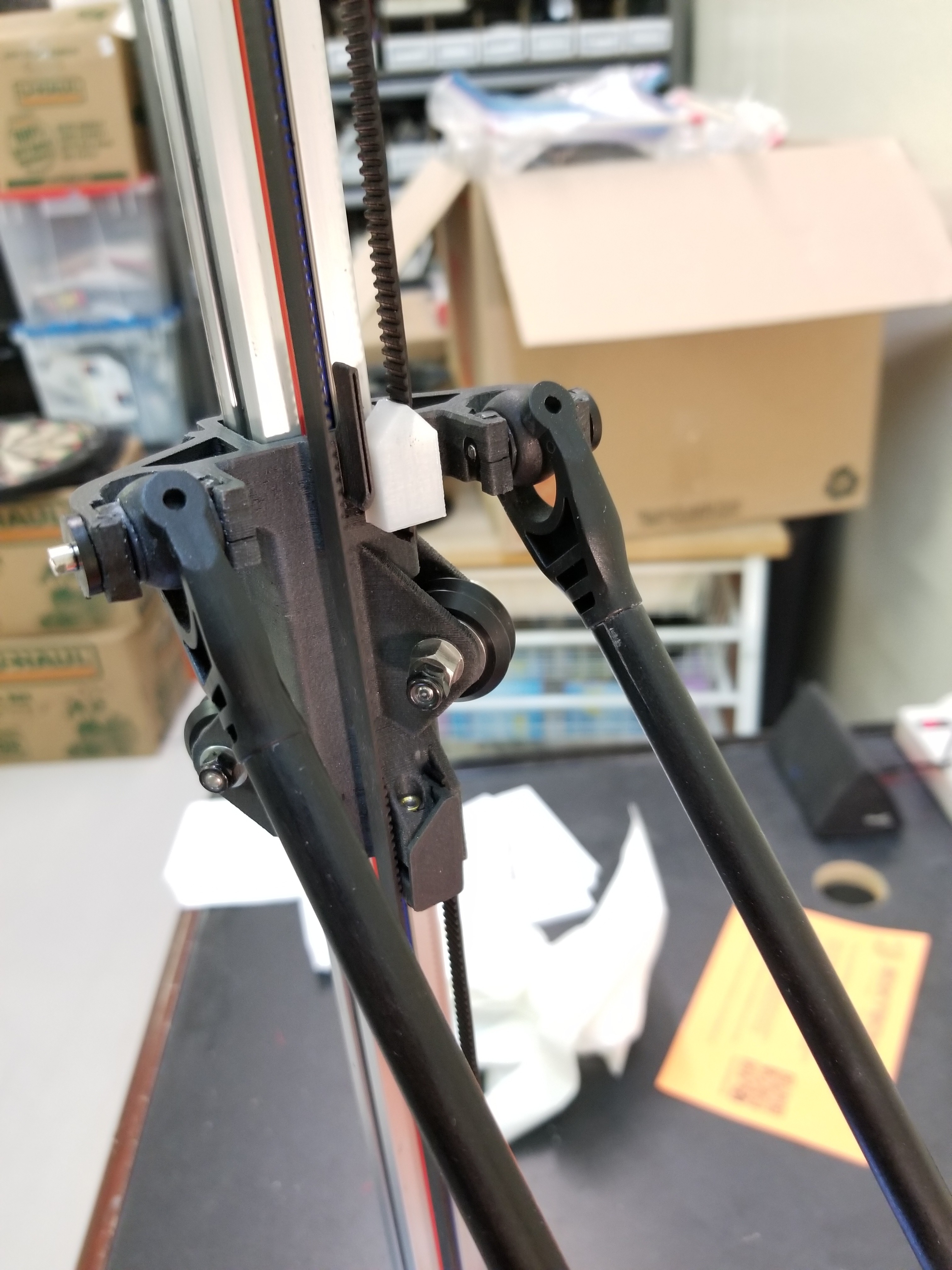
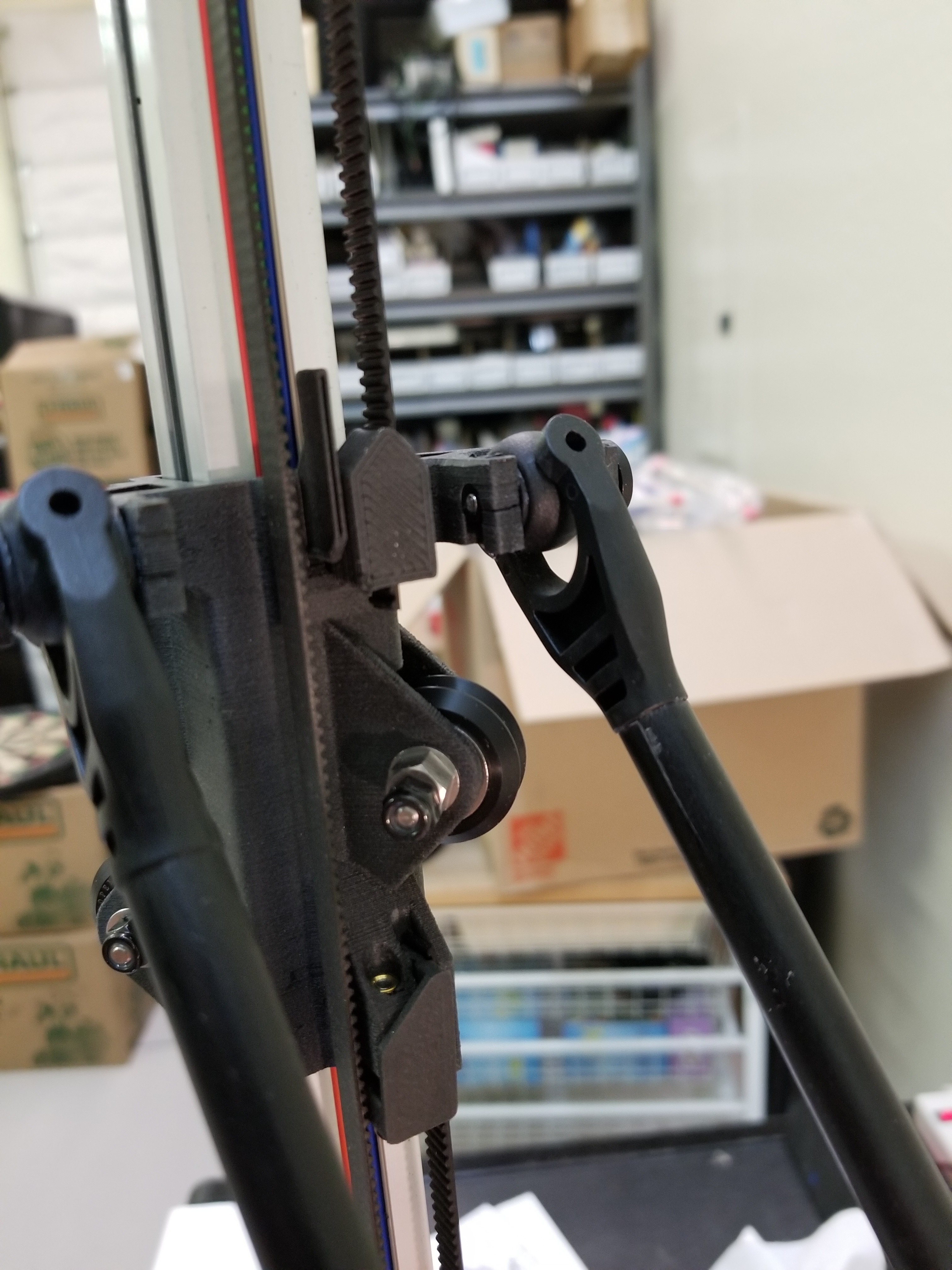
Look closely - the prototype fix for the first problem is the wart on top of the top belt clip - it's there to move the belt over a couple mm. Seems the designer put the belt holder in the <cough sputter> wrong place. Now what - I don't want to bodge any more of these up; just doing one was a real pain.
Luckily my old, tired and battered M3D printer was willing to come back to life - printed the hack in PLA.
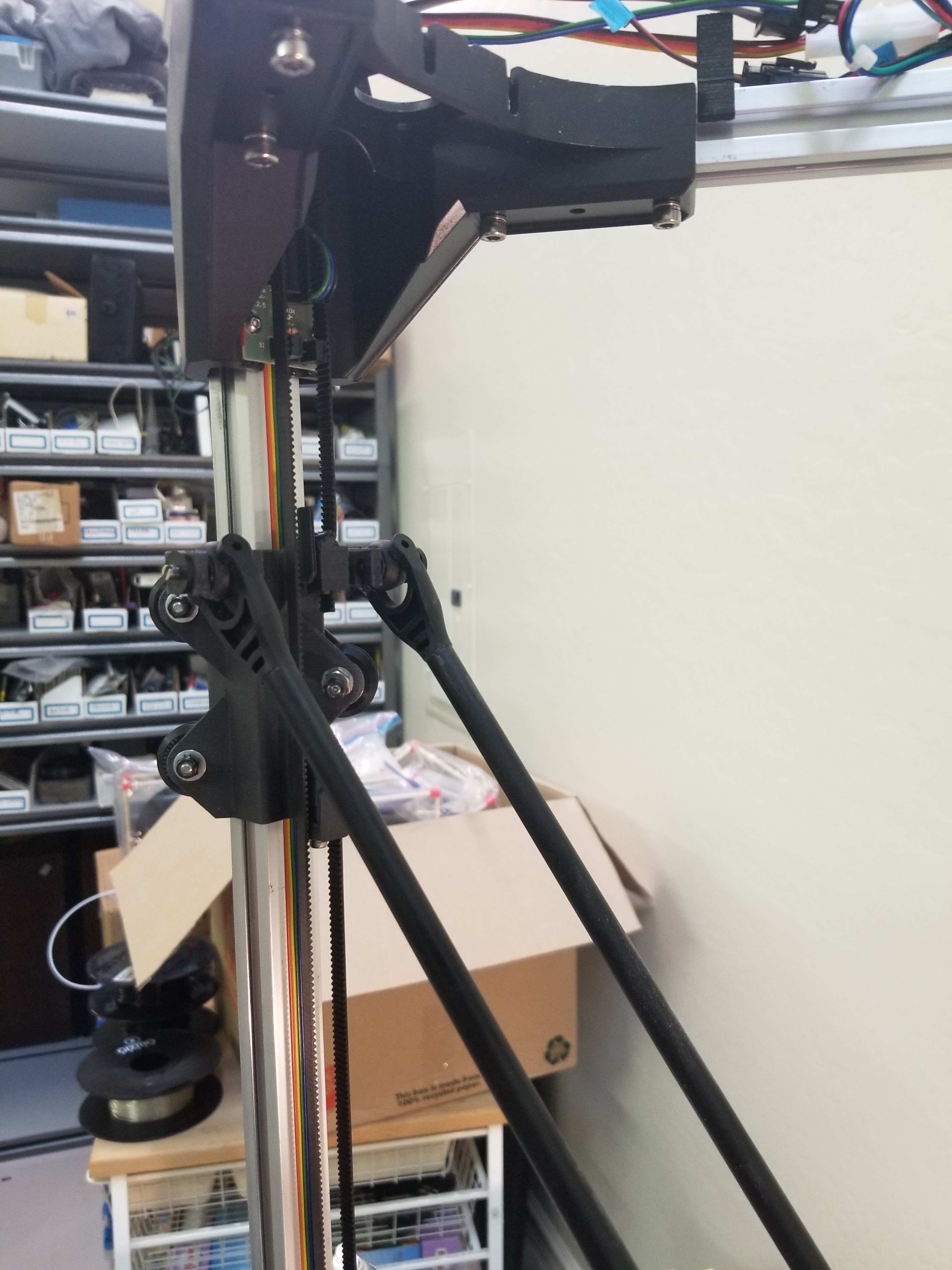
The printer was sufficiently functional at this point that I printed a set of clips in the same material as the carriage.
Oh but the second problem, which had manifested as difficulty moving the end effector towards the edges of the build platform, became clear. Look at what's happened to the printed part of the carriage that holds the rod bearings - they're cracked! What happened? Turns out the prints have a habit of over-extruding, up to 0.2mm, which caused the inner radius of the arms that hold the rod bearings to shrink. The U-joint part of the arm was banging against this inner radius, which caused this cracking.
Turns out a soldering iron and filament make for a good patch; which I wound up doing several times. My soldering iron doesn't like me any more.
After patching, extensive use of a rattail file and many test fits resulted in free movement for all the arms. All is well.
Another trick was to squirt some teflon lube into a cup, and paint some on all the bearing surfaces that were exposed in the process. This has resulted in much smoother action.
Discussions
Become a Hackaday.io Member
Create an account to leave a comment. Already have an account? Log In.