 brooksware2000
Introduction
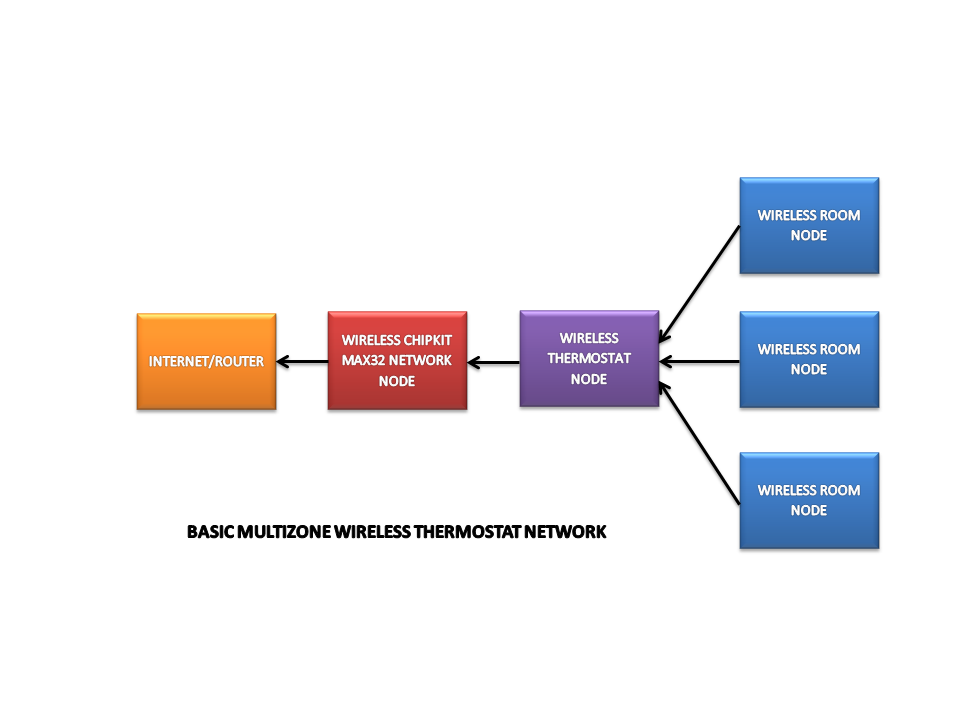
At the head of the setup is a router that provides internet access for the system. The first node is comprised of a chipKIT Max32, Max32 Ethernet Shield and XBee Shield (developed PCB). The second node is the Wireless Thermostat that is responsible for controlling the HVAC system and receiving data from the room nodes. The room nodes, with an output control board attached, can control a motorized damper to regulate the temperature in each room.
Communications
Here is a diagram the show a basic communication scheme for the wireless thermostat network.
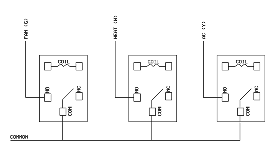
Wiring (Thermostat)
- The HVAC in my house has five wires and are marked as follows:
- RH – 24VAC transformer for the heating system. RH is wired to RC.
- RC – 24VAC transformer for the cooling system. RC is wired to RH.
- W – Relay that turns on the heat.
- Y – Relay that turns on the AC.
- G – Relay that turns on the fan.
The transformer connections RH and RC are wired together since there is only one transformer for the type of HVAC installed in my house. This transformer provides the power the thermostat uses to switch on the relays.
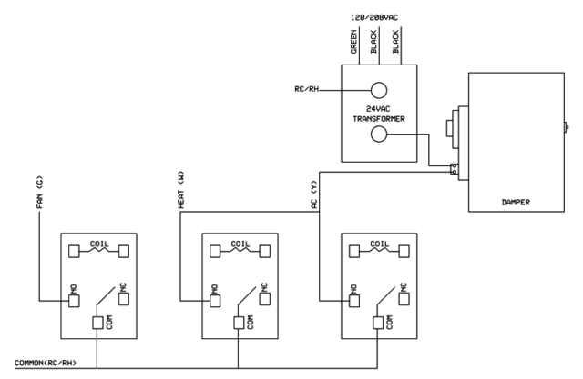
Wiring (Motorized Dampers)
Temperature control in each of the rooms is controlled by a motorized damper. The damper that I selected is a normally open type. This type of damper will close when 24VAC is applied to the motor. The damper will open when power is removed.
Power to the damper is controlled by the thermostat. Both the AC and Heat relays are wired together so that actuating either of them will provide power to the damper. The trip point for providing power to the damper motor is based on the mode of operation of the thermostat (heat/cool) and the temperature set point. This arrangement allows the wireless node placed in each of the rooms to individually regulate temperature.
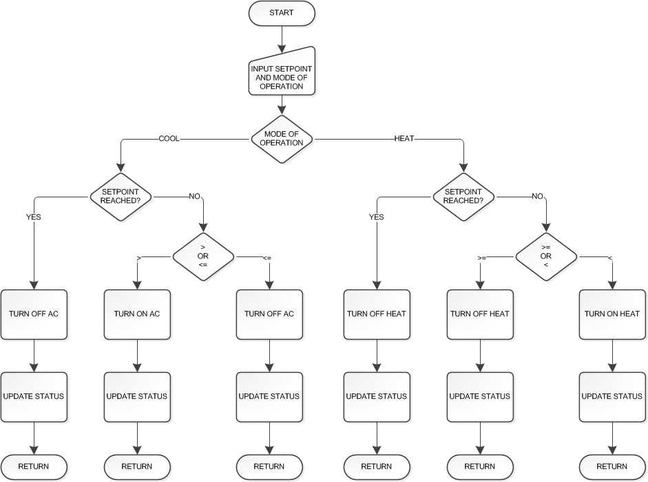
Operating Principles
The basic mode of operation for the Wireless Thermostat is to accept an input for a temperature set point and regulate the temperature around this set point. Regulation takes place through turning on or off the HVAC system.
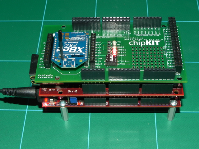
ChipKIT Max32 XBee Shield
The ChipKIT Max32 XBee Shield is a plug in board for the Max32 that allows for wireless communications via XBee modems. On the board is a dip switch that allows the default Serial1 port to be enabled or disabled. Serial port 1 on the Max32 was selected to allow the default port to remain free for sketch uploads. There is a 10 pin header on each side of the XBee modem connection that allows one to configure the board for other serial ports on the Max32.
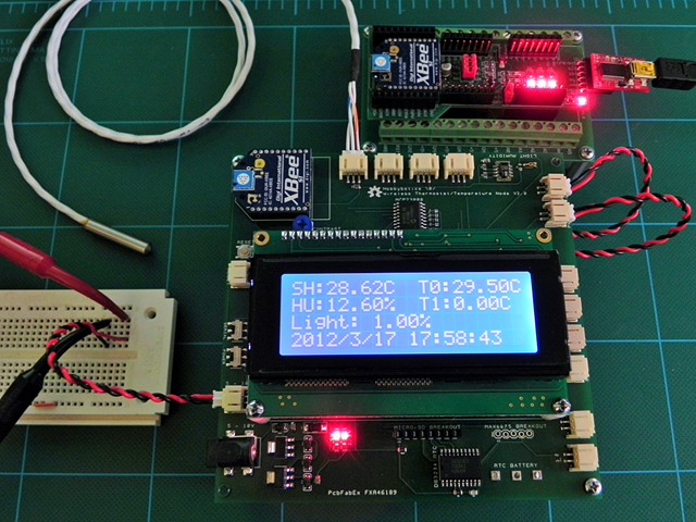
Wireless Thermostat/Temperature Node
The Wireless Thermostat/Temperature Node is responsible for controlling the HVAC and functioning as a room node to control the motorized dampers.
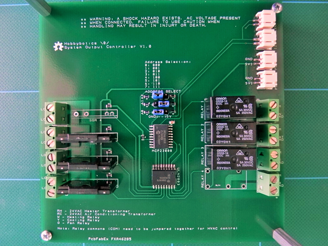
System Output Controller
The System Output Controller mates to the bottom of the Thermostat/Temperature Node. The board accepts I2C commands and controls the output of 4 Solid State Relays and 4 mechanical relays.
MAX6675 Thermocouple Breakout
The MAX6675 board was created as an attachment for the Thermostat/Temperature board to allow for Cold-Junction Compensated Type-K Thermocouple interface probes to be used. My plans are to use the design for various heating control projects such as a Sous-vide cooker, smoker controller, reflow oven and some environmental projects.
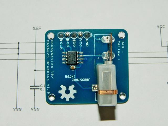
The specifications for the MAX6675 are:
- Works with any Type-K Thermocouple
- Has a range of 0 to 1024 degrees Celsius in 0.25 degree increments
- Operating voltage: 3.3 to 5V
- SPI interface
** NOTE ** The MAX6675 has been replaced by the MAX31855.
Pin List
| Wireless Thermostat/Temperature Node V2.0 Pin Assignments | |||
| Pin | Arduino Pin | Pin Name | Description |
| 1 | RESET | RST | Controller Reset Pin |
| 2 | D0/RX | RXI | Serial Receive (RX) Pin |
| 3 | D1/TX | TXO | Serial Transmit (TX) Pin |
| 9 | XTAL1/OSC1 | OSC1 | 16MHz Oscillator Pin 1 |
| 10 | XTAL2/OSC2 | OSC2 | 16MHz Oscillator Pin 2 |
| 8 | GND | GND | Ground |
| 22 | AGND | AGND | Ground |
| 7 | VCC | VCC | 3.3V |
| 20 | AVCC | AVCC | 3.3V |
| 21 | AREF | AREF | Internal Voltage Reference |
| 23 | A0 | DS18B20 | Dallas One-wire Temperature Sensor Pin |
| 24 | A1 | TEMT6000 | TEMT6000 Light Sensor Pin |
| 25 | A2 | SHT15_SDA | SHT15 Humidity/Temperature Sensor Data Pin |
| 26 | A3 | SHT15_SCL | SHT15 Humidity/Temperature Sensor Clock Pin |
| 27 | A4/SDA | MCP23008_SDA | MCP23008 I/O Expander Data Pin (I2C) Pin |
| 28 | A5/SCL | MCP23008_SCL | MCP23008 I/O Expander Clock Pin (I2C) Pin |
| 6 | D4 | MAX6675_DO | MAX6675 Thermocouple Data Pin |
| 11 | D5 (PWM) | MAX6675_CLK | MAX6675 Thermocouple Clock Pin |
| 12 | D6 (PWM) | MAX6675_CS | MAX6675 Thermocouple Chip Select Pin |
| 14 | D8 | SD_CD | Micro-SD Card Detect Pin |
| 15 | D9 (PWM) | SD_SS | Micro-SD Chip Select Pin |
| 16 | D10 (PWM) | SS | DS3234 Real Time Clock (RTC) Chip Select Pin |
| 17 | D11 (PWM)/MOSI | MOSI | DS3234
Real Time Clock (RTC)Data In Pin
Micro-SD Data In Pin |
| 18 | D12/MISO | MISO | DS3234 Real Time Clock (RTC) Data Out Pin
Micro-SD Data Out Pin |
| 19 | D13/SCK | SCK | DS3234
Real Time Clock (RTC) Clock Pin
Micro-SD Clock Pin |
| 4 | D2/INT0 | INT_SQW | DS3234 Real Time Clock (RTC) Interrupt Pin |
| 5 | D3 (PWM)/INT1 | MENU | Interrupt Driven Menu Button |
Notes
- MCP23008_SDA, MCP23008_SCL and MCP23008_SCL pins are shared by MCP23008 input/output Expanders. The first expander is connected to the 4X20 LCD and has address 0. The second expander is connected to the menu buttons and has address 1.
- Additional expanders may be connected to the controller (address 0 and 1 are reserved).
- The MENU button is connected to interrupt 0. This allows program execution to be interrupted and control branched back to the main menu routine.
- DS3234 RTC SQW/INT pin is connected to interrupt 1. This allows the controller to detect a 1sec pulse from the RTC.
Wrap Up
This project presented some DIY methods to allow one to gain remote access to a multi zone thermostat system in order to monitor and control temperature regulation. The overall goal was to demonstrate how a DIY Internet connected wireless thermostat system can be cost effectively developed. The design of the project is very flexible to allow future expansion into appliance control. The code presented with this project is basic and was designed as a starting point for future development. For now, all of the project files are located at the following link until I have an opportunity to finish of the code.