 Stefan Lochbrunner
Enumeration
So I started writing this log yesterday and while doing so checked the Pro Trinket HID example again. (As mentioned in the tutorial, it is based on the VUSB for Arduino library. Mentions of any files refer to the ones from this library.) Turns out they updated it with some more information that provides the solution to a problem I had. Specifically, they added their usbconfig.h file in the learn section. Taking a closer look at it shows that they commented out the definitions in the "Optional Hardware Config" part in usbconfig.h which causes the device to re enumerate by pulling D- to GND (see usbdrv.h for details). The possibility of this is unfortunately not mentioned in that section, which only describes the option to implement a (dis)connect by connecting the D- pull-up resistor to an output pin instead of Vcc. While forcing D- to GND
"does not conform to the spec, but [] works,"
as stated in usbdrv.h, it's way more convenient so that's what I'll use (as does the bootloader I assume).
However, for completeness (or whatever) I'll share what I initially did to get the Pro Trinket to re enumerate. The first thing I tried was to see if the bootloader would work with the pull-up connected to PD5. It didn't. (What I should have done was to look into how the bootloader handles re enumeration. Adafruit Pro Trinket bootloader github -> main.c, uses (dis)connect functions, check included files -> usbdrv.h, see lines 299 and following.) But after the bootloader timed out, the device enumerated as HID keyboard for the first time. Therefore, what I was planning on doing was to have a switch to select where to connect the pull-up resistor. Either to Vcc for programming or to any convenient free pin when used as a keyboard. The switch can be seen in the upper right.
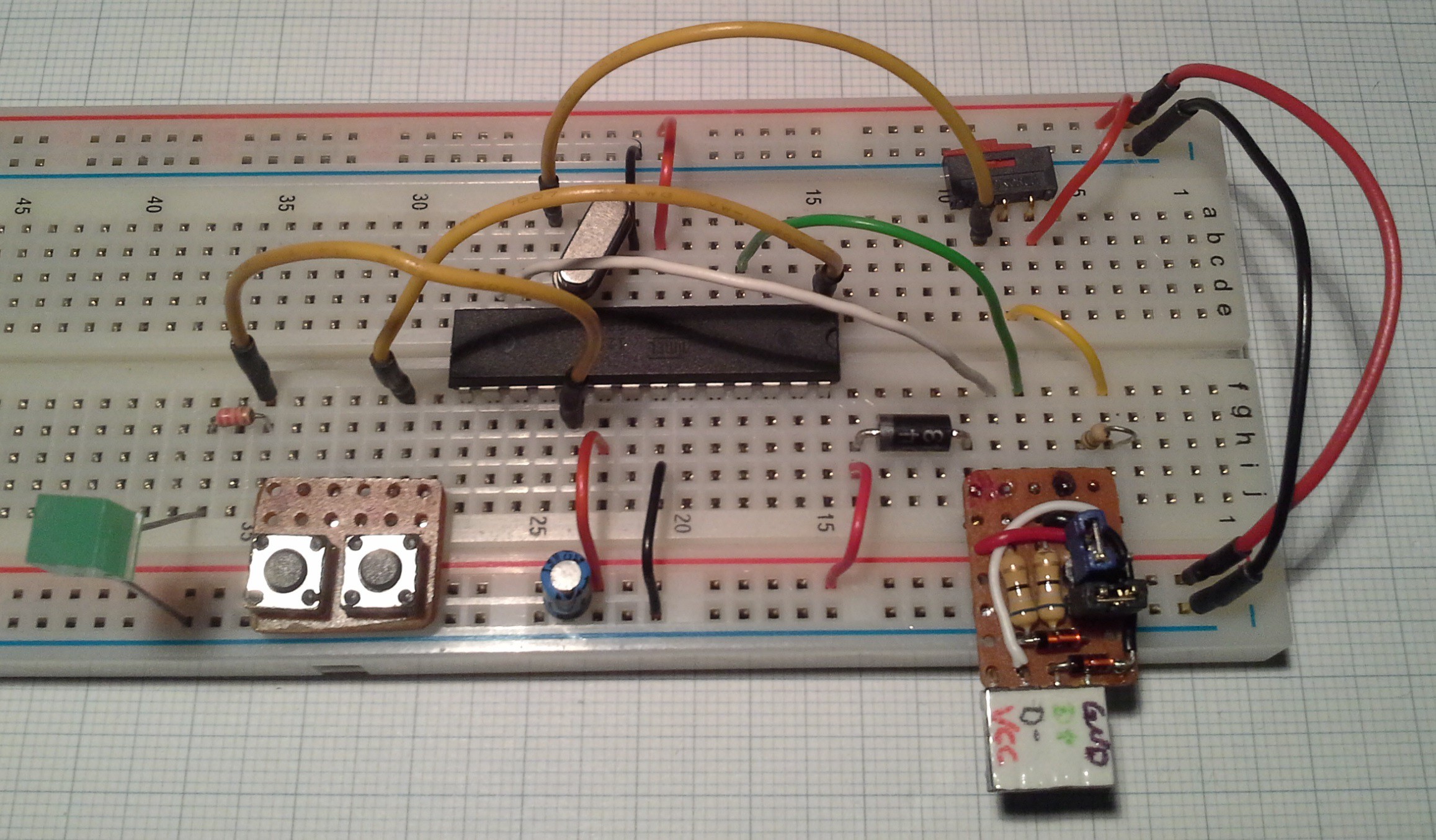
For clarity I'd also like to mention, while on the topic of USB, that the thing in the bottom right is just the basic "VUSB circuit" with 3.6V zener diodes to GND and 68 Ω resistors in series. Initially the pull-up resistor was also on the board roughly where the white wire originates at the D- marking. Later I also broke out the D- line to be able to control the pull-up. Additionally the board plugs into the power rails and can be connected to them via the two (black and blue) jumpers. To conform to the Pro Trinket schematic (ironic since I didn't bother adding capacitors at the crystal) Vcc is here connected to the power rail via a Schottky diode and not by setting the blue jumper. </tangent>
USB polling
Unfortunately I don't remember where I read that the USB connection should be polled (or updated as it's called in this library) quite often. This is also done in the Trinket USB Volume Knob example, where not really much else is done if no input occurs. From what I had read on the subject, it was my understanding that the time set in the usbconfig.h file (USB_CFG_INTR_POLL_INTERVAL, default 10ms) was a maximum time after which a poll would be conducted at the latest in case the execution of the user code prevented a poll. Maybe this is still the case and it is just coincidence that if I don't delay my code by 10ms (with the delayMs function) it doesn't execute properly. While using the delay worked fine for reading a 3x4 button matrix, it didn't work for reading a rotary encoder since the event of turning it takes less than 10ms as shown below:
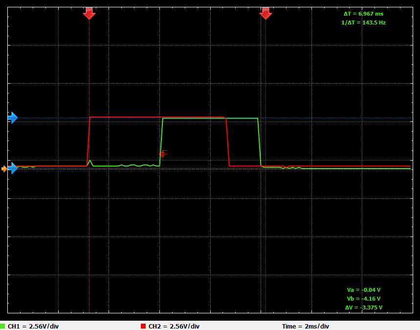
The two channels correspond to the A and B pins of a rotary encoder. The assignment of channels to pins is for this measurement irrelevant. (I used a Xprotolab Plain to capture these signals. It's nice little device but that DS1054Z would definitely come in handy, shameless plug ;) )
Therefore reading an encoder only every 10ms is clearly insufficient. To decrease the time between readings while maintaining the delay between USB polls I measured the execution time of a single program cycle without any additional delay, which came out to around 164µs.
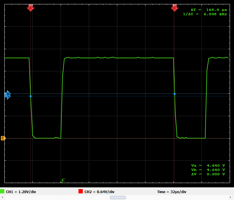
Shown here is one program cycle which consists of four polling cycles for the four keypad columns.
At a cycle time of 164µs, the required delay of at least 10ms is obviously achieved by executing 61+ cycles. Using this cycle time the two pins of the encoder are read around 40 times during the 7ms it takes to turn the rotary encoder by one notch which allows for quite reliable operation.
This covers two of the biggest issues I had so far. In the next (major) log I'll go into more detail on how I implemented polling the keypad and rotary encoders.
Discussions
Become a Hackaday.io Member
Create an account to leave a comment. Already have an account? Log In.