 Stefan Lochbrunner
Now that sending of keystrokes over USB works as desired it's time to add the inputs. As mentioned before, the aim is to have 12 buttons (in a 4x3 keypad) and 4 rotary encoders.
Keypad
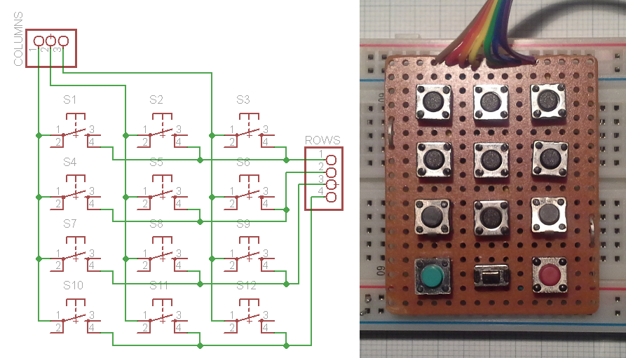
I'll be using encoders that also have a push button integrated. Those buttons will be part of the keypad but for prototyping I soldered up a dedicated keypad (out of whatever tact switches I had on hand).
Via a quick search I found the Arduino keypad library that sounded pretty good since it would allow me to use 12 buttons with only 7 pins instead of potentially 12 pins. Initially I tested the library on a Pro Mini to be able to see output via the serial interface and it worked really great but when I tried it in combination with the VUSB for Arduino library I ran into trouble. Since the keypad library uses the delay function for software debouncing of the buttons, disabling timer0 for USB is problematic.
In an attempt to solve this problem I tried implementing this functionality myself. In case you don't know how it works, here's the basic gist: Only one column (e.g. column 1) at a time is set high while the others remain low. Now all the rows are read and if one or multiple rows are asserted (e.g. rows 2 & 3) this means that the corresponting button is pressed (in the above schematic for column 1 and rows 2 & 3 this would mean that buttons 4 and 7 are pressed). This is the basic version of how I did it:
(because I use the internal pull-up resistors these signals are active low which is the opposite of the small example)
//cycle through cols
for(int i=0; i<cols; i++){
   //enable col (active low)
   digitalWrite(colPins[i], LOW);

   //poll rows
   for(int j=0; j<rows; j++){
      //read state of current btn
      key_state[j][i] = digitalRead(rowPins[j]);

      //button is pressed, active low
      if(key_state[j][i] == 0){
         //execute keystroke
         UsbKeyboard.sendKeyStroke(usb_codes[j][i]);
      }
   }
   //disable col
   digitalWrite(colPins[i], HIGH);
}
// /cycle through cols
This will send a keystroke (corresponding to the key defined in the usb_codes array) every time the state of a button is evaluated as being pressed, which could potentially around 6000 times a second as discussed in a previous project log. Therefore a mechanism to only trigger a keystroke if a button is pressed but not when it's held is required. To do this I employ a variable to save the state of the previous button readings and one more condition as shown here:
key_state[j][i] = digitalRead(rowPins[j]);

//btn was just pressed, current state 0 prev state was 1
if(key_state[j][i] == 0 && key_prev[j][i] == 1){
   //set new prev state
   key_prev[j][i] = 0;

   //execute keystroke
   UsbKeyboard.sendKeyStroke(usb_codes[j][i]);
}
//key release
else if(key_state[j][i] == 1 && key_prev[j][i] == 0){
   //set new prev state
   key_prev[j][i] = 1;
}
Once a button is released the key_prev variable is reset and another button press can be recognized. In my test this worked quite well and felt very responsive so let's move on to the next part.
Rotary encoders
In another project with a rotary encoder I was just polling the two pins without using interrupts. Since it worked pretty good that's what I tried first.
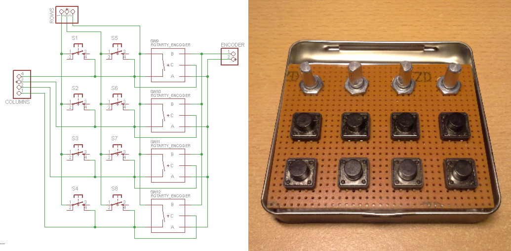
To implement the encoder polling into the previous code I followed the same principle as above and set it up to be active low (again, to utilize the internal pull-up resistors). That way I can use the signals that select a column to also select/enable one of the rotary encoders and detect on two additional input pins in which order the pins of the encoder go low. The order in which the pins are asserted of course corresponds to the direction in which the encoder is turned. Incorporating the 4 rotary encoders into the keypad then looks like this:
And here's the code to make it work:
//poll encoder
int A = digitalRead(encPins[0]);
int B = digitalRead(encPins[1]);

//detect rotation
if(A == 0 && enc_prev[i] == 1){
   //change prev state
   enc_prev[i] = 0;

   //determine rotation direction (cw/ccw)
   if(B == 1){
     //cw rotation ...orwhatever?

     //execute keystroke
     UsbKeyboard.sendKeyStroke(usb_codes_enc[i][0]);
   }
   else if(B == 0){
      //ccw rotation

      //execute keystroke
      UsbKeyboard.sendKeyStroke(usb_codes_enc[i][1]);
   }
}
else if(A == 1 && B == 1){
   //no input on encoder pins
   enc_prev[i] = 1;
}
// /poll encoder
What this does is it looks at one of the two encoder outputs and once it is asserted (remember, active low therefore A == 0) it evaluates the other output. Depending on the direction of rotation, if one of the two outputs (e.g. A) is being asserted, the other one will either still be not asserted (B == 1) or will already have been asserted (B == 0). To understand this it helps to look at the output of a rotary encoder:
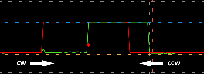
Here the horizontal axis is the time and the vertical axis the signal. The direction of rotation then corresponds to moving through the traces either left to right or right to left.
The Adafruit Trinket USB volume knob project (which I kept in mind in case my approach wouldn't work out) uses a similar mechanism but employs direct port access for better performance which I didn't find necessary in terms of responsiveness.
And this is what it looks like with the keypad and rotary encoders attached:
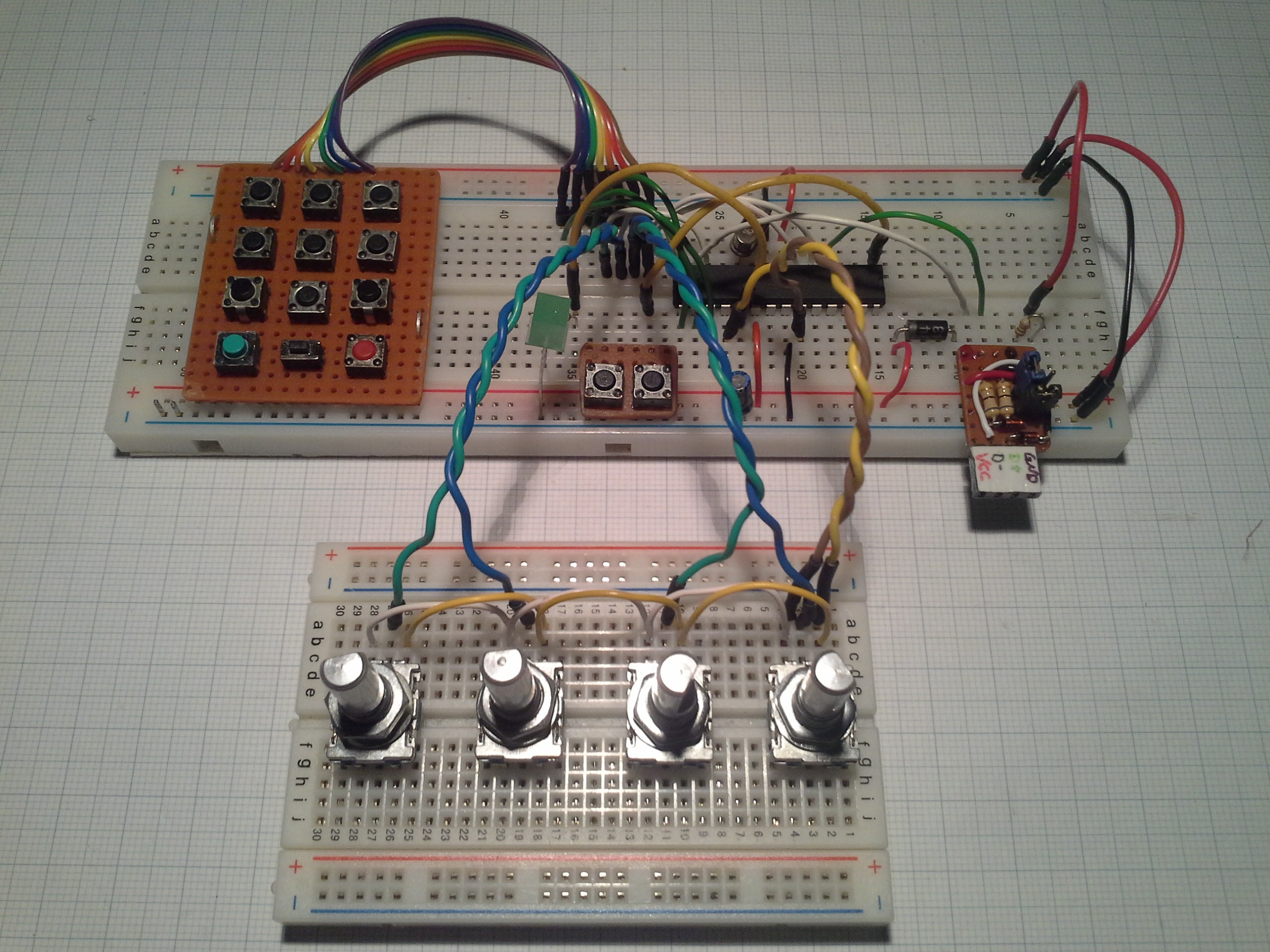
Note that I still use all the buttons on the keypad instead of substituting one column by the switches in the encoders. I don't think it will make much difference and this way I saved some wiring that would make it more confusing.
The 3 pairs of twisted wires actually worked quite good, while keeping the encoders in contact with the breadboard was somewhat problematic. It was only when I probed the A and B outputs that the twisted wires distorted the signal.
Concluding remarks
I hope this explains sufficiently how the keypad and rotary encoders work in this system. I'm somewhat hesitant to post the complete code since it's not really optimized and has some redundancies that would make it harder to follow what's (supposed to be) going on. Quite often I only find parts of projects helpful and am not interested in replicating the whole so hopefully you can use this information in your (maybe USB unrelated) project. However, once the code is done I'll definitely post it.
The same goes for complete schematics. I plan on changing the pins a bit to free up PWM capable pins for LEDs. Since this isn't using interrupts you can use whatever pins are available, it should be pretty straightforward.
Another thing regarding the usage of interrupts is that it might be more reliable for the keypad and especially for the rotary encoders but since the purpose of this device is translating key presses into USB and the responsiveness of it is quite good I'll stick with polling the inputs for now.
Discussions
Become a Hackaday.io Member
Create an account to leave a comment. Already have an account? Log In.