 Stefan Lochbrunner
This week I finally received my order from DirtyPCBs (after anxiously waiting for about a month):
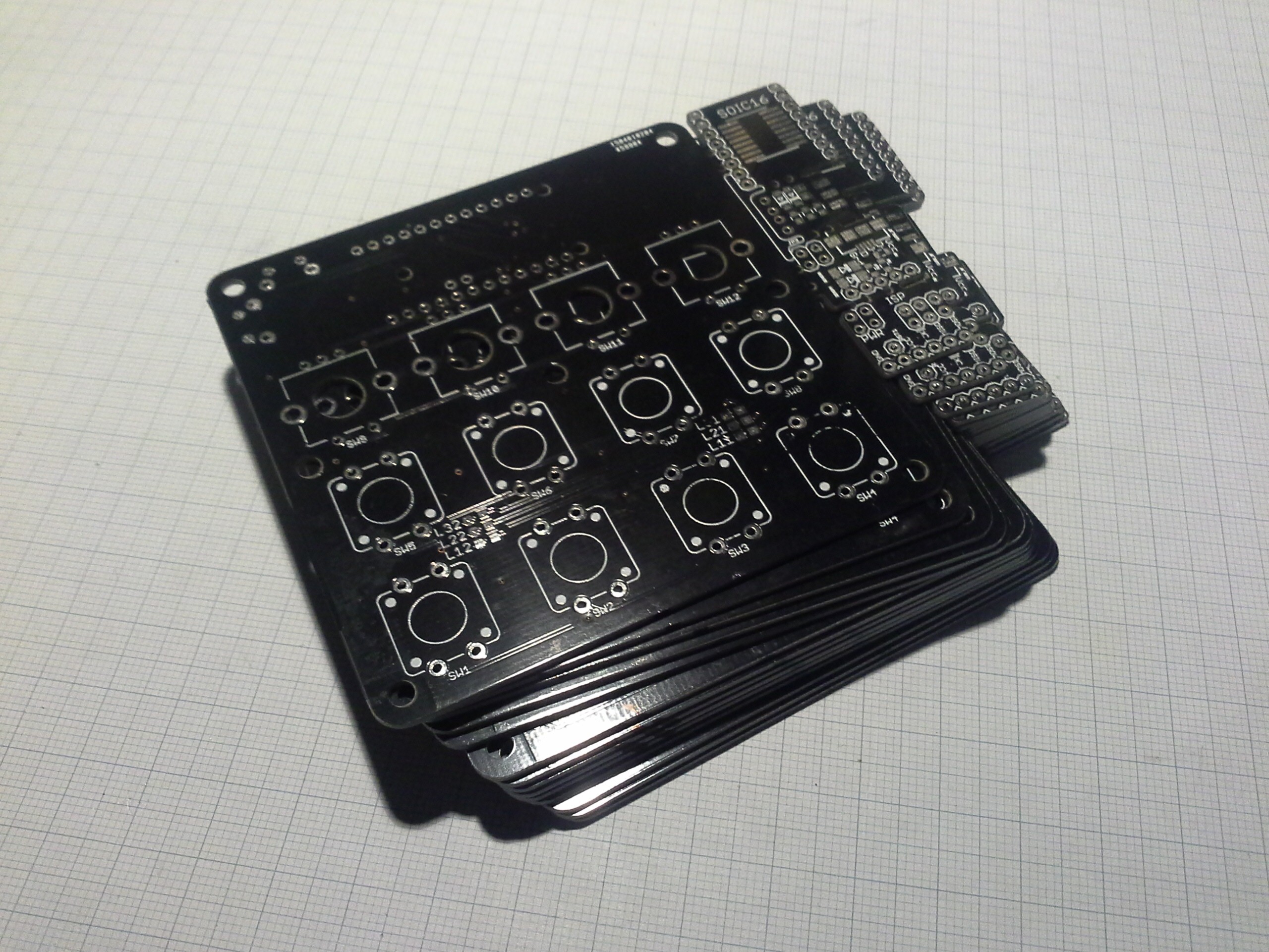
To make better use of the area I added some breakout boards and some other things I wanted to try out. Besides some silkscreen issues on a few boards they turned out great and for that price I can't complain.
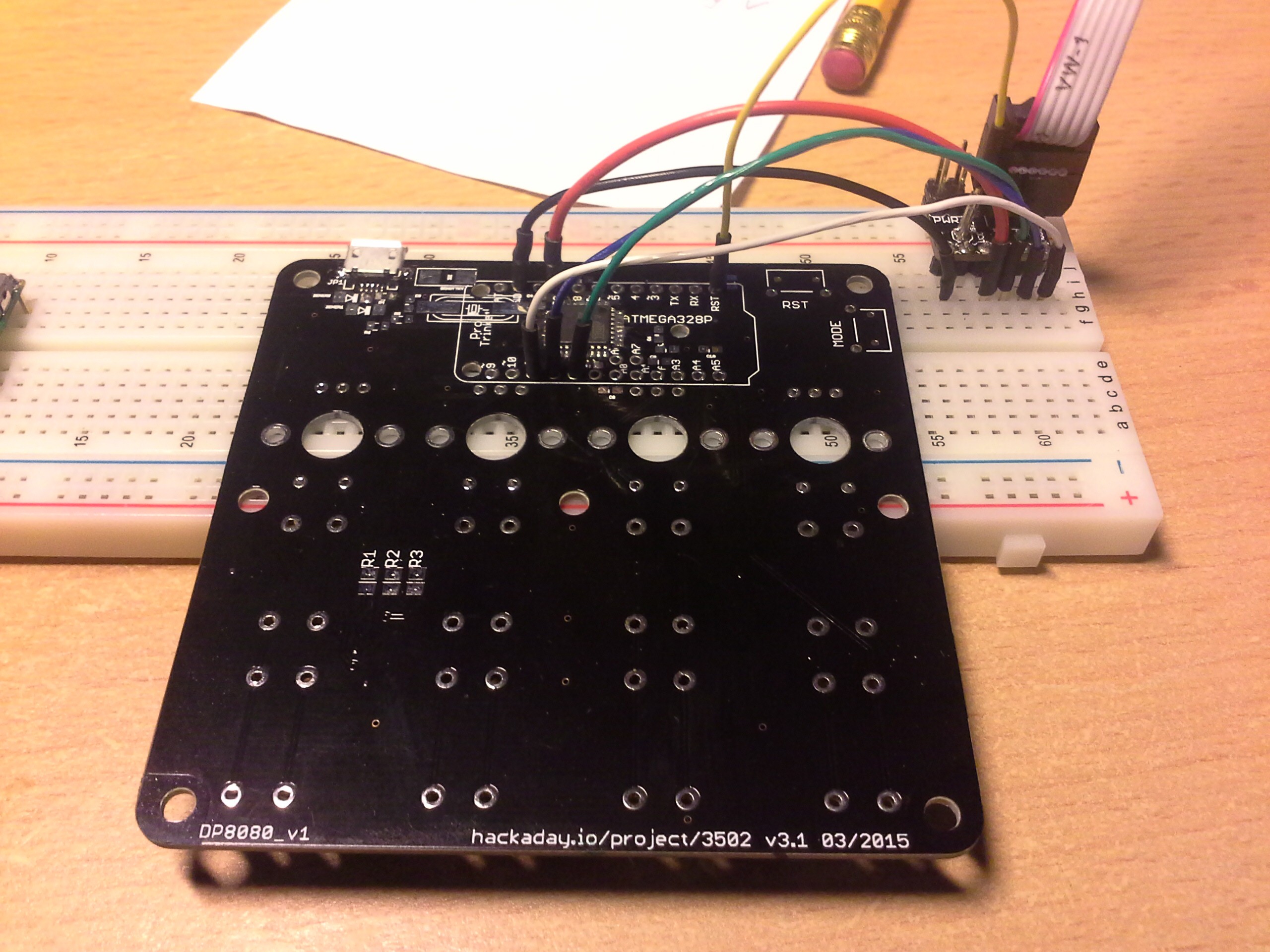
If you looked at the schematics and board layout you might have noticed that I left out an ISP header. Routing the reset signal to the other side of the chip where the MOSI, MISO and SCK pins are just seemed like too much work if I could access these signals via the Pro Trinket footprint. Therefore, to program it I put it on a breadboard and made the connections with jumper wires:
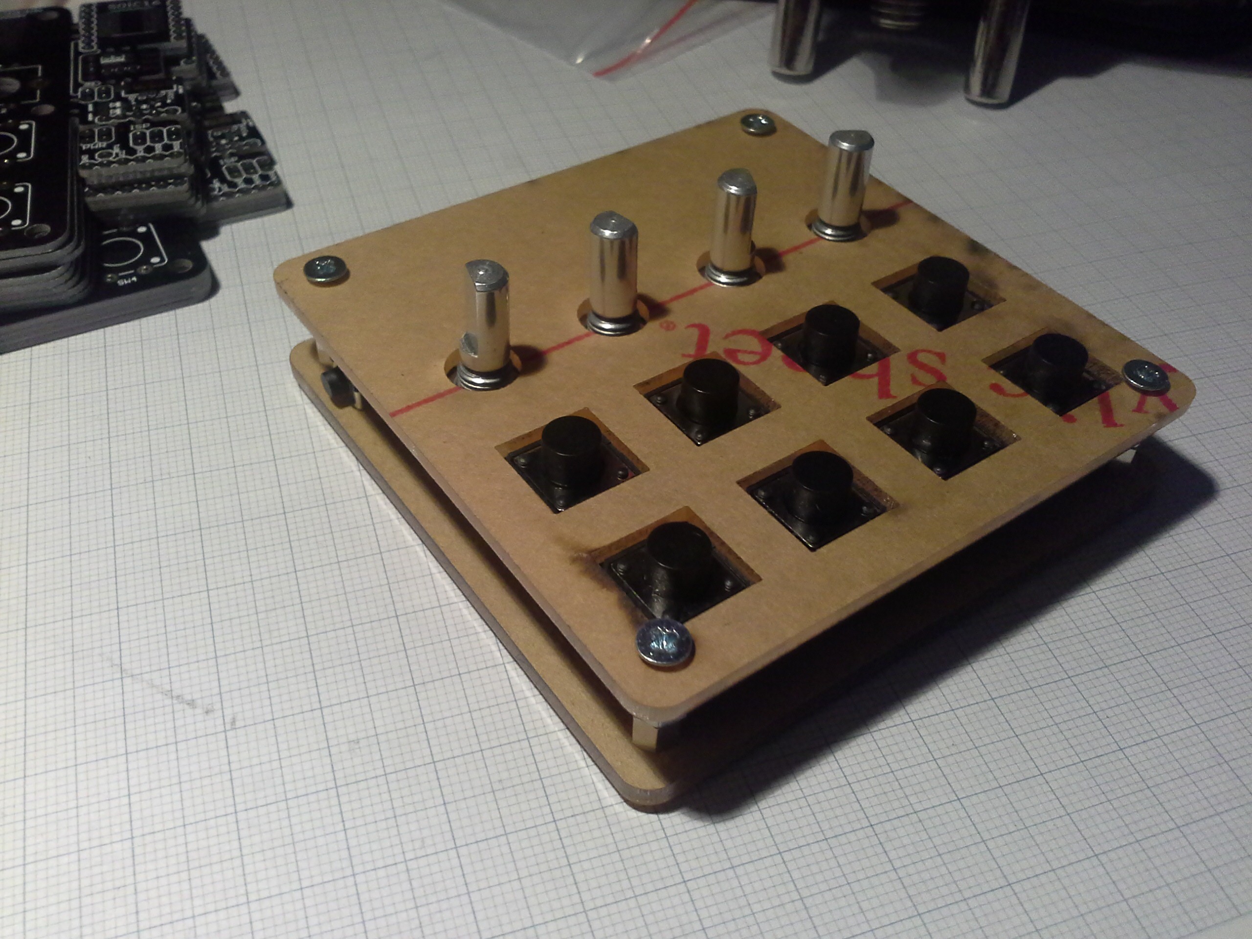
While I was waiting for the PCBs I also received the custom acrylic pieces for the top of the case...
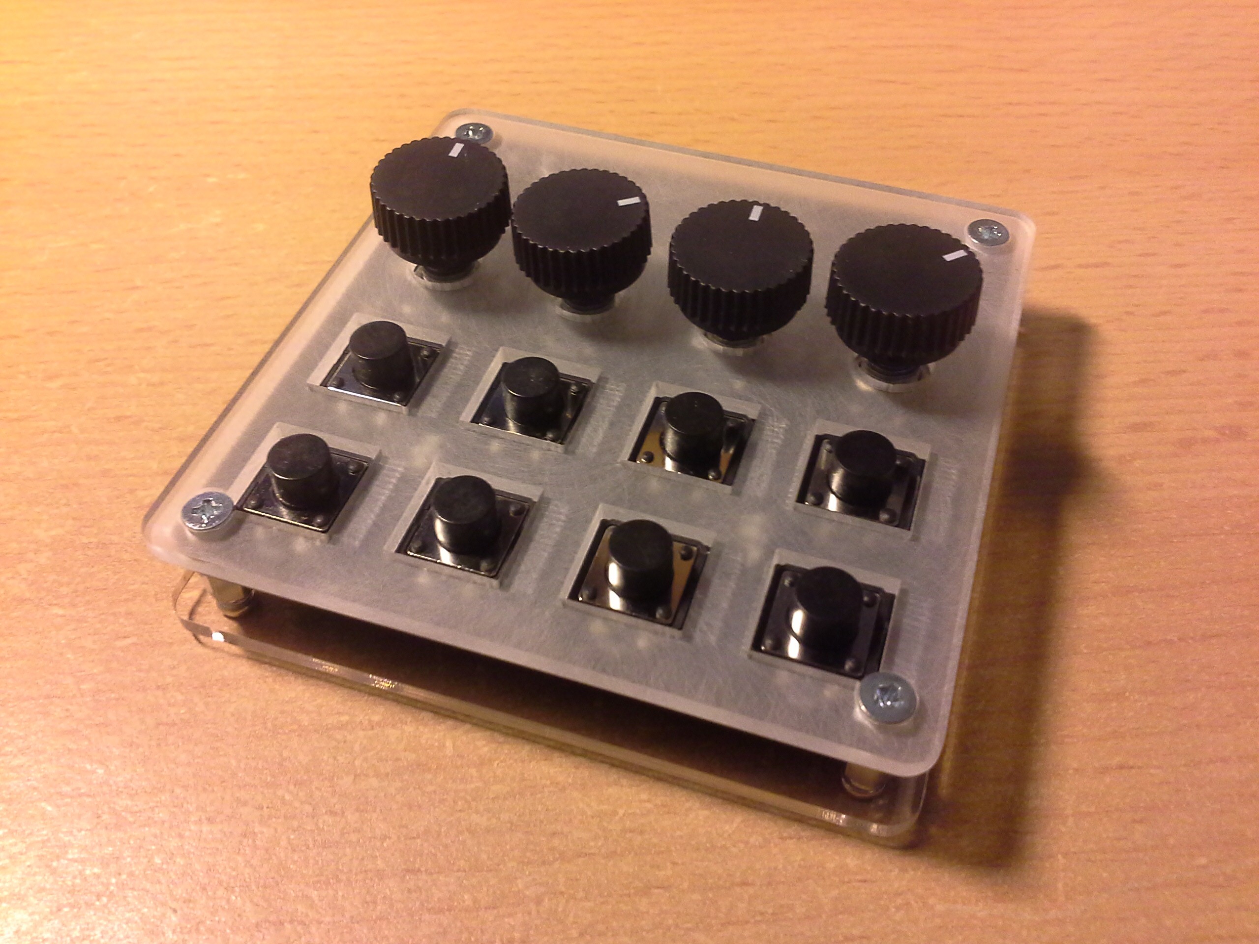
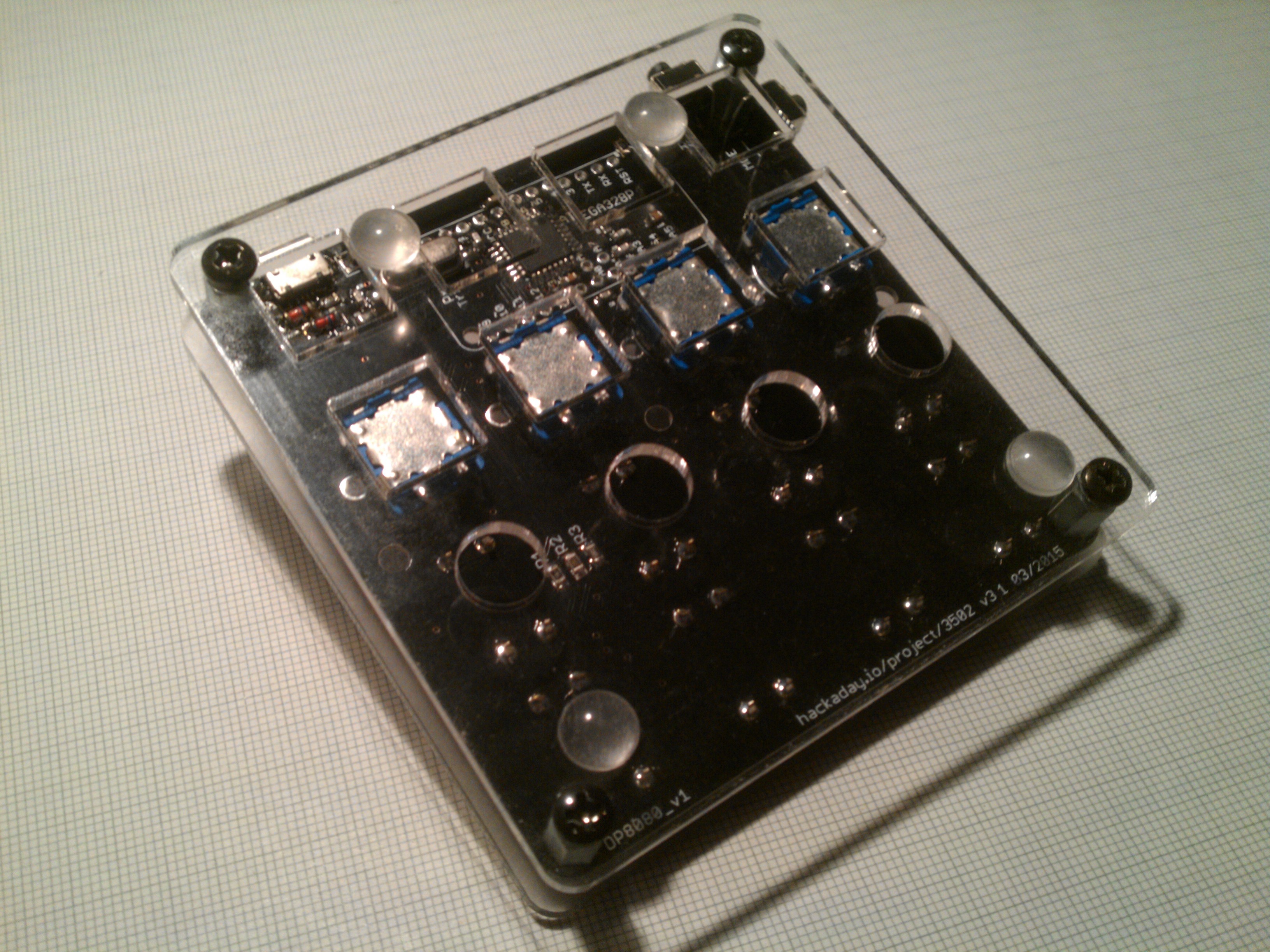
All in all I'm really happy how everything turned out:

As mentioned in another log, I had to change some pin assignments due to some differences in the pinouts between the DIP and the TQFP. The updated sketch is on GitHub as V2.
Another thing I mentioned was the occasional bouncing in the prototype. Unfortunately this problem still persists (mostly when quickly tapping a button quickly) but that's what I added the capacitor footprints for. However, even without the capacitors the keyboard is quite usable since using a shortcut doesn't require fast typing... and I'm surely not going to write a project log with it.
Adding the capacitors brings up another issue, which is that a charged capacitor will cause the neighboring button in the next column to be read as pressed as well. The solution to this is to add enough delay between activating the columns to allow the capacitor to discharge below a certain threshold. I'll look into this some other time but for now I consider this project done.
Update 2015-10-20:
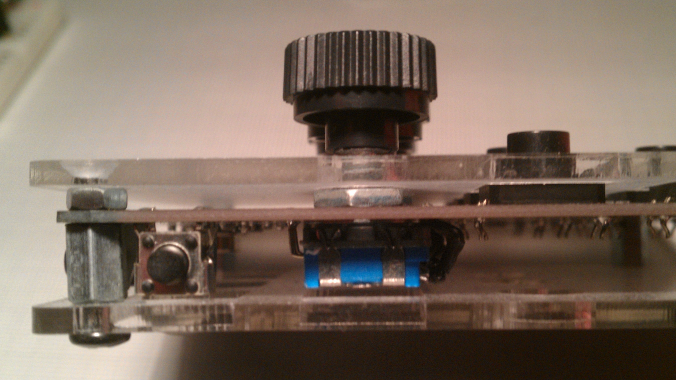
Some more pictures to clarify assembly:
Bottom side:
Mode button on left side:
Discussions
Become a Hackaday.io Member
Create an account to leave a comment. Already have an account? Log In.
thanks for the update :)
Are you sure? yes | no