 jaromir.sukuba
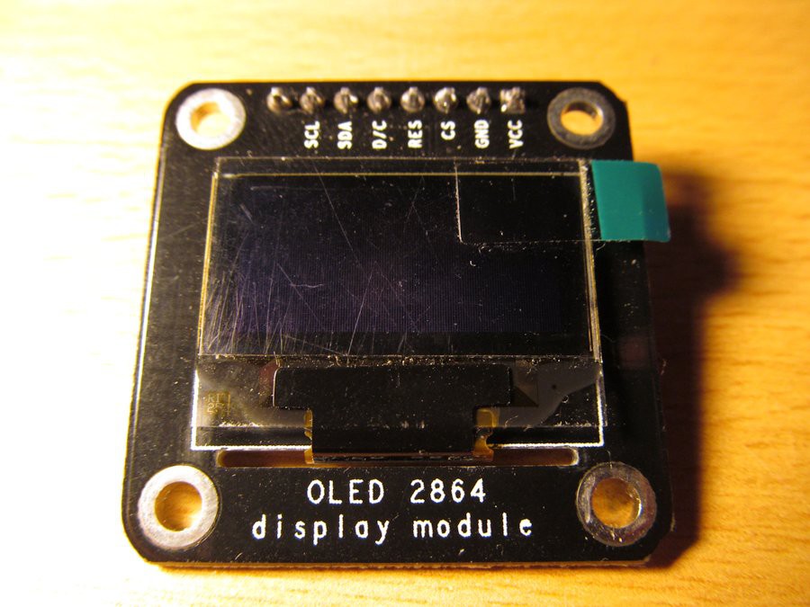
Somewhere in corner of my junkbox I found this beautiful OLED display.
"Great display for Pavapro", I thought to myself.
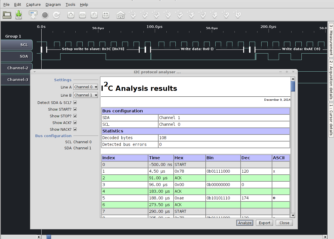
Nothing could be easier than wiring this tiny OLED with absolutely classic SSD1306 driver, apparently in SPI mode - look at the signals, D/C, CS, plus clock and data. I downloaded datsheet of driver and started writing simple driver library. I had experience with the display in I2C mode and already knew it is not that hard. I wrote all the code, with software SPI implementation and everything was great except of the fact the display was completely blank. Logic analyser (this with this software, great multiplatform combo) showed no problems with SPI code, initialization ran as expected, but display was not amused at all.
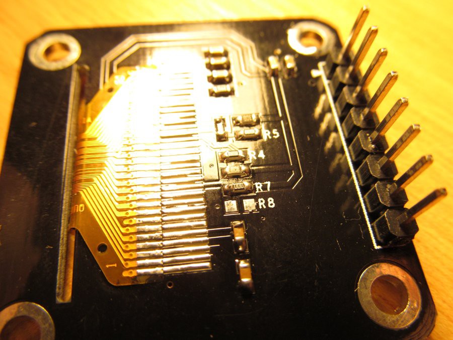
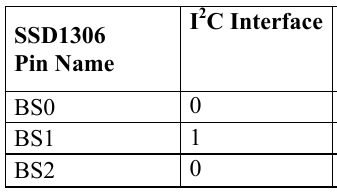
After one evening full of adjusting parameters, changing SPI modes and pulling my hair I remembered I ordered I2C display, not SPI one! I flipped the display board and looked at tje OLED panel pinout. 30-pin 128x64 OLED, this seems to be jellybean part, like this one http://www.adafruit.com/datasheets/UG-2864HSWEG01.pdf. The pin 11 is interesting - it is BS1 pin, along with BS0 and BS2 allows to change the way the display talks to your MCU (https://www.adafruit.com/datasheets/SSD1306.pdf ). In this case only BS1 is interesting, as others are hardwired to SPI/i2C interface and this BS1 does the selection. And this is how it looks on the other side:
Well, I reworked my code to use I2C interface and it works, as expected. By the way, I love my logical analyser
Oh yes, I almost forgot: I could save a lot of debugging by reading the frikkin' manual. Look here (leading to wiki):
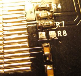
OLED display module supports IIC or SPI communication with default as IIC. If you want to use SPI communication, following settings will be needed: Remove resistors on R3, R4, R5, and R7, and weld a 0R resistor on R8.
Ouch.

Discussions
Become a Hackaday.io Member
Create an account to leave a comment. Already have an account? Log In.