-
Tuesday Update
12/16/2014 at 13:37 • 0 comments![]()
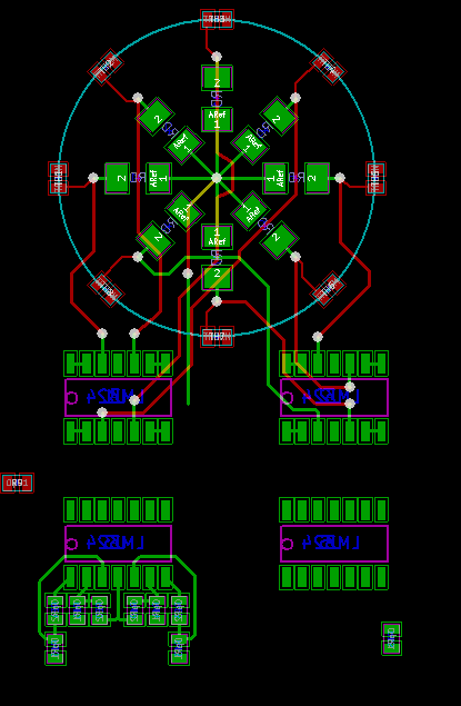
Layout is a fairly tedious process. But I'm making progress. I dedicated most of the weekend to other household tasks that were also being neglected, so I'm still struggling to get this done. I'm not sure if all programs are quite the same as KiCad, but I really hate how cludgey the interface is for layout. Unless I'm missing some tips and tricks, it takes at least 8 clicks to orient each resistor the correct way. Right click, footprint, flip. Right click, footprint, rotate +.... very annoying after only a few resistors. Oh well, I certainly don't have time to write my own so that's what I have to deal with.
Plans are to finish this layout and start working on some software on the breadboard. I'm pushing it to have it assembled by the January deadline for the contest, so I have to start on that as well.
A few extra notes on this layout. My main goal is only have the thermistors on the top. All other components will be on the bottom so they do not disrupt the air flow. Thermal design is important as well, as the sensors should not be getting heat via the board from other components, or at least not unevenly. With the exception of the divider resistors, nothing else should generate much heat. I will have to be careful with the traces running to power the dividers, as that could generate heat. There probably will be some inequities between the sensors, so hopefully any variations can be accounted for in software.
One more thought, while I want little thermal mass attached to the thermistor so it can easily be heated at low power, I am debating putting some bare copper pads for extra heat dissipation ability. I will probably just stick to the normal pads I have now, but thats possibly a future sensitivity improvement method.
-
Friday Notes
12/12/2014 at 19:01 • 0 commentsSometimes it's good to meditate on stuff for a bit, esespecially when your an amateur like myself. I realized to properly use my difference amp I need to use some buffer amps on all the input voltage dividers, otherwise the gain resistors become part of the circuit and screw up all my calculations. So I'm just going to pile more amps onto the board. That was the last part of the design that was bugging me, so I really have to put in a late night to get that board on order. January approachs.
Also, skipping to software for a second, I think I'm going to try this Visual Studio add in for developing the code. http://www.visualmicro.com Since I work in VS everyday at my real job, it's worth a try just for familiarity.
-
Monday Notes
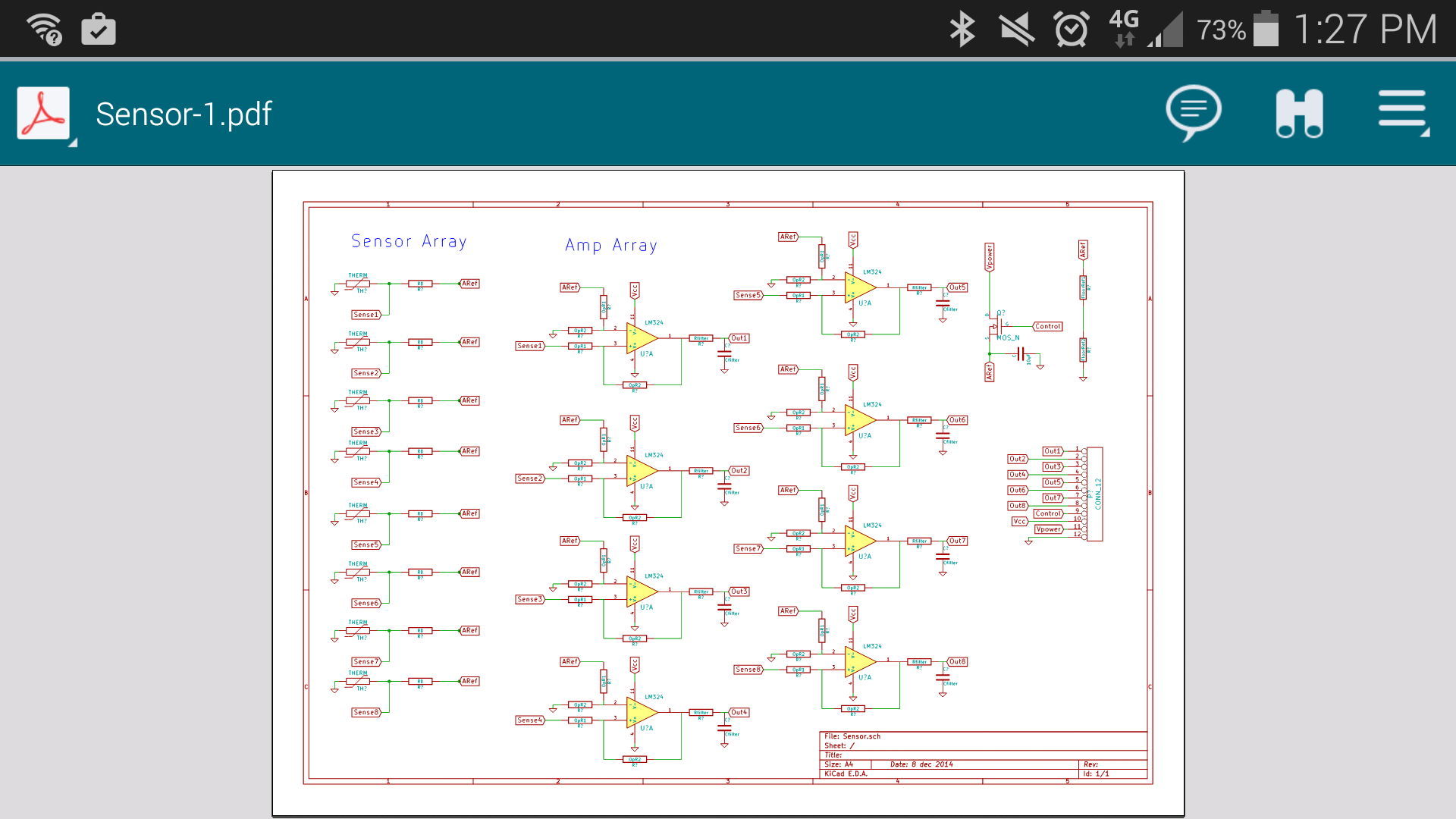
12/08/2014 at 19:31 • 0 commentsOne of the Trinket contest rules for the weekly drawing is that you have at least one project log with a picture. Since I'm still in design mode, heres a screenshot of my schematic on my phone.
![]()
Also this is the quad op amp im going to use.
http://search.digikey.com/scripts/DkSearch/dksus.dll?Detail&name=MCP6L04T-E/SLCT-ND&site=US&lang=en
Layout is still the next chore to be done. I'll set a goal to have that on order by the end of the week.
-
Progress Update
12/08/2014 at 02:20 • 0 commentsI just committed a schematic of my proposed circuit to the linked GitHub. The current design is 8 sensors, that consist of a simple voltage divider, powered by a PWM control from the micro, fed into an op-amp, through a low pass filter out the the 8 analog inputs on the micro. Included with the KiCad files, there is a PDF of the current schematic as well as an excel file that I was using for my component calculations. You may notice on the schematic that there are not a lot of values specified. This is mostly because the circuit works with lots of combinations of values, thus the worksheet. Next up is the layout.
As an aside, I'm happy to see that I have 6 followers on this project, a good incentive to make it work. Thank you! I'm not a trained EE, so I welcome any advice, though I may limit my design decisions to the ones I understand, at least at first.
-
Ballpark Math
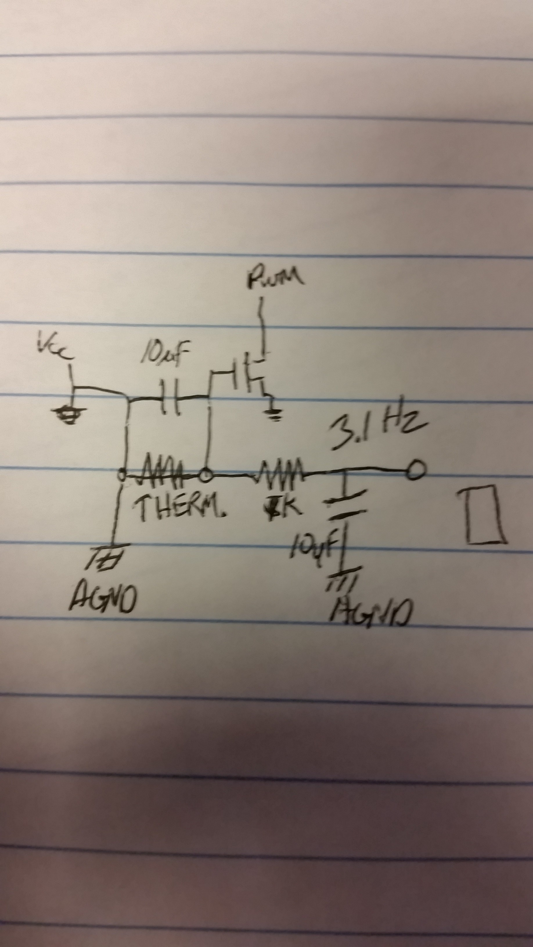
12/03/2014 at 18:02 • 1 commentI'm working out the resolution of my sensors, to see what changes I will be able to detect. With my thermistor in a simple 50/50 voltage divider, the values given in the data sheet for the thermistor, and 5V source, I'm looking at 4mV change per degree C. Given the onboard ADC is 10 bit, that works out to about 4mV resolution. That's about 1°C resolution.
That doesn't sound good enough to do what I want, granted I have no idea what temperature change will be associated with a particular air flow. I also don't know how hot I will be able to get the thermistor. This is important since the higher above ambient the device is, the easier it will be to detect increased heat dissipation. I also am planning to use the micro to control the voltage to set the average temperature of the array. So I don't know the voltage across the sensor either. Also since this is used outdoors, I have to assume the voltage required to keep a certain level above ambient will vary.
It's doesn't sound like I know a lot, which presents a challenge in designing a circuit that will work across that range, or ah least be fixed by swapping a few resistors or in software. I do plan on at least leaving a footprint on the sensor board for a higher resolution ADC. Speed isn't an issue, so hopefully a reasonable resolution and cost effective ADC could be found. Also, another option is to use a op amp to provide high gain on the output and adjust the signal to use more of the ADCs range. Some quick math shows a gain of 8 could be used, of we wanted to use the thermistors full range. That would give 1/8 degree resolution. Higher gain could be used of we refine the temp range we will use it at.
I'll put down some of these calculations later, to hard on mobile. (Lunchbreak)
-
Part Shopping
12/03/2014 at 03:47 • 0 commentsThermistor: Digikey PN 541-1169-1-ND, THERMISTOR PTC 330 OHM 1% 0603
Also, even though the Trinket appears to have 8 analog inputs, I'm going to leave a space for a MAX11629EEE+-ND, ADC 12BIT 300KSPS 8CH 16-QSOP on the sensor PCB, so it can be standalone if needed.
I'm thinking of using 8 thermistors for the array. I think the small 0603 package will give leave it with a small thermal mass to be sensitive to small flow changes.
-
Sensor Design
12/02/2014 at 13:14 • 0 commentsThe trick with making a wind sensor is that most are normally larger than your pocket with moving parts. After reviewing my options for solid state sensors, I've decided that my best bet is to use thermistors, which will be powered(to generate heat) and monitored. The idea is that an the speed of the wind will increase the rate at which the thermistor can dissipate heat, which we will be able to measure. A small plastic shroud will catch the different directions of wind passing them over separate thermistors on a small pcb. Additionally a MEMS compass will be included so the N/S/E/W direction of the wind can be easily known.
I'm hoping to also include a small LCD, some touch sense buttons, and a SD slot for logging the data.
![]()
Wind Measurement
A simple pocket tool to measure and log wind speed and direction.