 Jac Goudsmit
Ohio Scientific (OSI) was a company that produced many 6502-based computers in the late 1970s and early 1980s. One of those computers was the Superboard II, also available in a case as the Challenger C1P. In the UK, many people may remember the CompuKit UK101 which was a clone of the Superboard II, available as a kit from a magazine. The Superboard II doesn't use IRQ or NMI interrupts, generates character-based monochrome video, and the original machine only had 4KB of memory. This makes it a great candidate to be replicated on the L-Star hardware.
As I may have mentioned before, I worked with Vince Briel at Brielcomputers.com on a replica of the Superboard II last year, so I had some code laying around from that project: a modified 1-pin TV driver that can handle the 256-character OSI font, and an OSI keyboard emulator.
The Propeller has 32 digital I/O pins, of which 25 are used by the address bus, data bus and R/~W line. Two pins are more or less reserved by the serial connection to the PC and two are used by the I2C EEPROM that stores the Propeller program (the 6502 clock is generated on the I2C clock line). That leaves only 3 pins for other I/O. Two are used for the PS/2 keyboard, and one is used for video.
One Pin TV Driver
You may wonder how the Propeller can generate an analog video signal on a single digital pin. The secret is that it uses one of the built-in timers to generate a high-frequency block wave. The impedance and capacitance of the connected monitor reduces the high-frequency signal into a DC-level, which is interpreted as black. The Propeller sets the pin LOW for blanking and synchronization, and it sets it HIGH for white.
The 1-pin TV driver was written by a few members of the Propeller forums as a means for debugging programs, but originally, it was written in such a way that it wouldn't have worked for the Superboard II emulator. For one thing: it stored the font in the cog, which made it incapable of displaying the 256-character OSI font: the font data would have taken up the entire cog, not leaving any memory space for the code. So I modified the code to read the font from the hub. This reduces the maximum resolution a bit (hub access is much slower than cog access), but we should never need more than 64 characters per line, which is well within the limits of the modified driver.
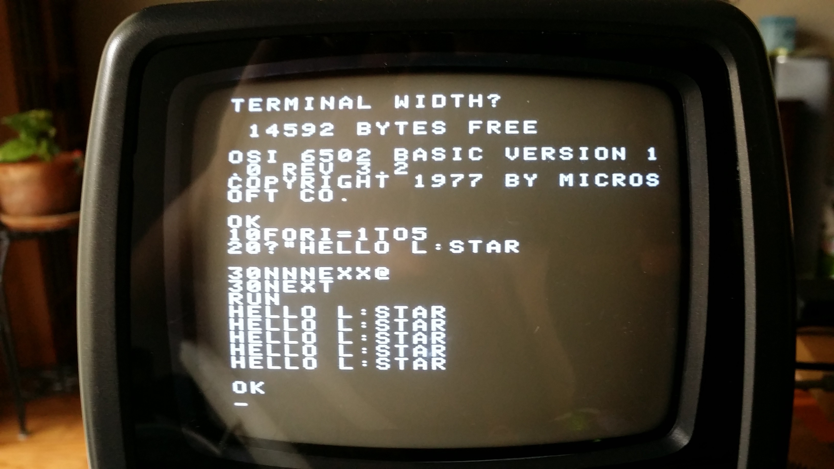
The original Superboard II video hardware was a very simple circuit. It generated 32x32 characters (totaling 1KB of video memory) of monochrome video at 60Hz (50Hz in Europe). But the characters around the edge would be in the non-visible areas of most screens, so the software only used 25 lines of 25 characters in the middle of the screen. I modified the 1-pin TV driver so that the first character that's displayed doesn't necessarily have to be the first character in the video buffer. And at the end of each row of characters, the driver adds a number to an address, to make a few characters invisible. That way, the line addresses are still (say) 32 addresses apart, but only (say) 25 characters per line are visible.
For now, the 1-pin TV driver is hardcoded to emulate the Superboard II display with the 1KB memory (32x32 characters). The parameters can easily be changed to change the video to 48x32 or even 64x32. Some of the original video adapters for other OSI computers were capable of switching between two modes (e.g. 32x32 and 64x32) by writing to a specific address in memory; this is currently not possible because the video parameters are calculated at compile time; however I'm planning on changing this in the future.
OSI Keyboard Driver
All computer keyboards are implemented as a matrix of switches: Each key is connected to one row and one column of electric lines. The computer activates a row, and then checks which column(s) is/are active to see which key switch connects that row to a column. In modern computers and in your PS/2 keyboard, the computer that takes care of scanning the keys has been replaced by a microcontroller. Simply said, the microcontroller in a PS/2 keyboard translates the scanned keys to a serial signal, which is sent to the host computer (the host computer can also send signals to the keyboard to turn the LEDs on or off).
But in old computers such as the OSI Superboard II, the computer was directly connected to the keyboard matrix, Obviously this has disadvantages: the computer won't see a key press if it doesn't scan the matrix every once in a while. We may not be able to change that, but we do have to translate the data from the PS/2 keyboard into scan data.
On the Superboard II, the 6502 stores a value to location $DF00 to activate the rows of the keyboard matrix, then it reads back from the same location to find out which column(s) on that row have their switches pushed down. It's possible (to an extent) to detect multiple simultaneous key presses, and the keyboard matrix on the Superboard II was especially designed to make sure that simultaneous pressing of the shift, shift-lock and repeat keys together with other keys would never be a problem.
The OSI keyboard driver has to do the reverse of what the controller in the PS/2 keyboard already does: it has to convert the incoming serial data from the keyboard back to a keyboard matrix that the software will understand. The work to do that is divided between two cogs: the first cog executes pretty much the same code as the original PS/2 driver included with the Propeller software, the second cog monitors the 6502 address bus and data bus to check if any keyboard scanning is going on.
Instead of generating an ASCII code or a scan code, the first keyboard cog keeps track of a table of which keys are currently pressed. The PS/2 protocol allows multiple keys to be pressed at the same time (not all keyboards support this equally well but that's a different problem) so the cog can simulate simultaneous pressing of keys. The table matches the keyboard matrix of the original OSI, and stores a bit value of 1 for each key that's currently pressed. When the second cog detects that the 6502 is scanning the keyboard by writing a value to $DF00, it basically changes the index of the byte in the table that Propeller will present to the 6502 when it does a read from $DF00.
The value that the 65C02 stores at address $DF00 can't be used directly. There are 256 possible values of the byte that the 65C02 may store at the location, but there are only 8 rows. On the real hardware, it would be possible in theory to activate multiple columns at once, but if we would emulate this, it would take a lot of extra code, and/or a lot of extra memory. Instead, the driver implements a compromise: as long as the 65C02 only scans one row at a time, it will get accurate results, but if it tries to scan multiple rows at the same time, it gets the columns for the row with the highest number. To accomplish this, the Propeller code uses a table that it generates at runtime, containing the base-2 log values for values 1 to 255.
ACIAThe cassette port of the Superboard II was connected via a Motorola 6850 ACIA (serial port controller). At this time, that chip isn't emulated yet. I will fix that soon: the serial port to the PC can then be used with a terminal program to save or load programs.
Discussions
Become a Hackaday.io Member
Create an account to leave a comment. Already have an account? Log In.