 Jac Goudsmit
Last Friday, the Rev. 4 boards arrived from OSHPark, and a Purple PCB Day is always a good day. Also, BBC America was doing their Star Trek 50th Anniversary Marathon of all the Original Series episodes and I was the only one home, so this was going to be a fun night of watching the young version of Khan, Zefram Cochrane and the Tribbles, and soldering my project together. Or not?

Just Kitting
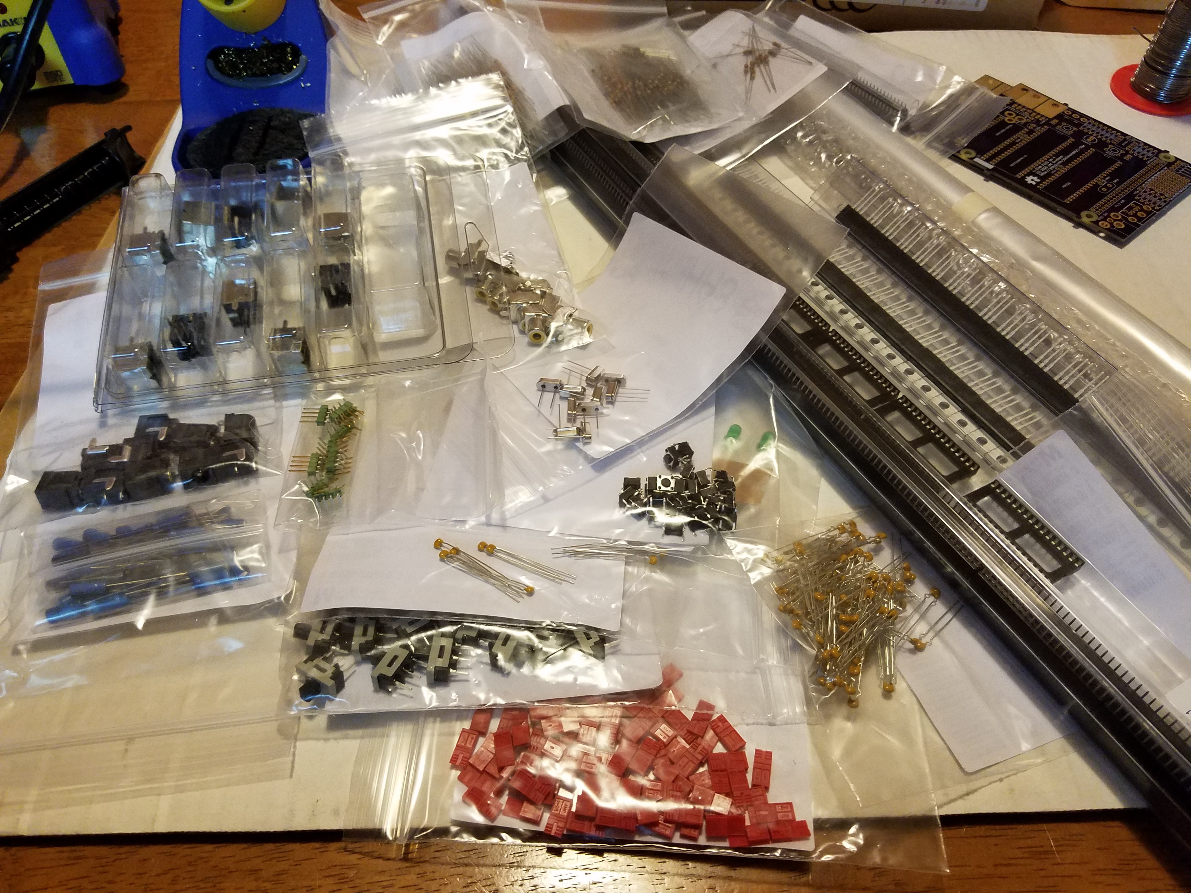
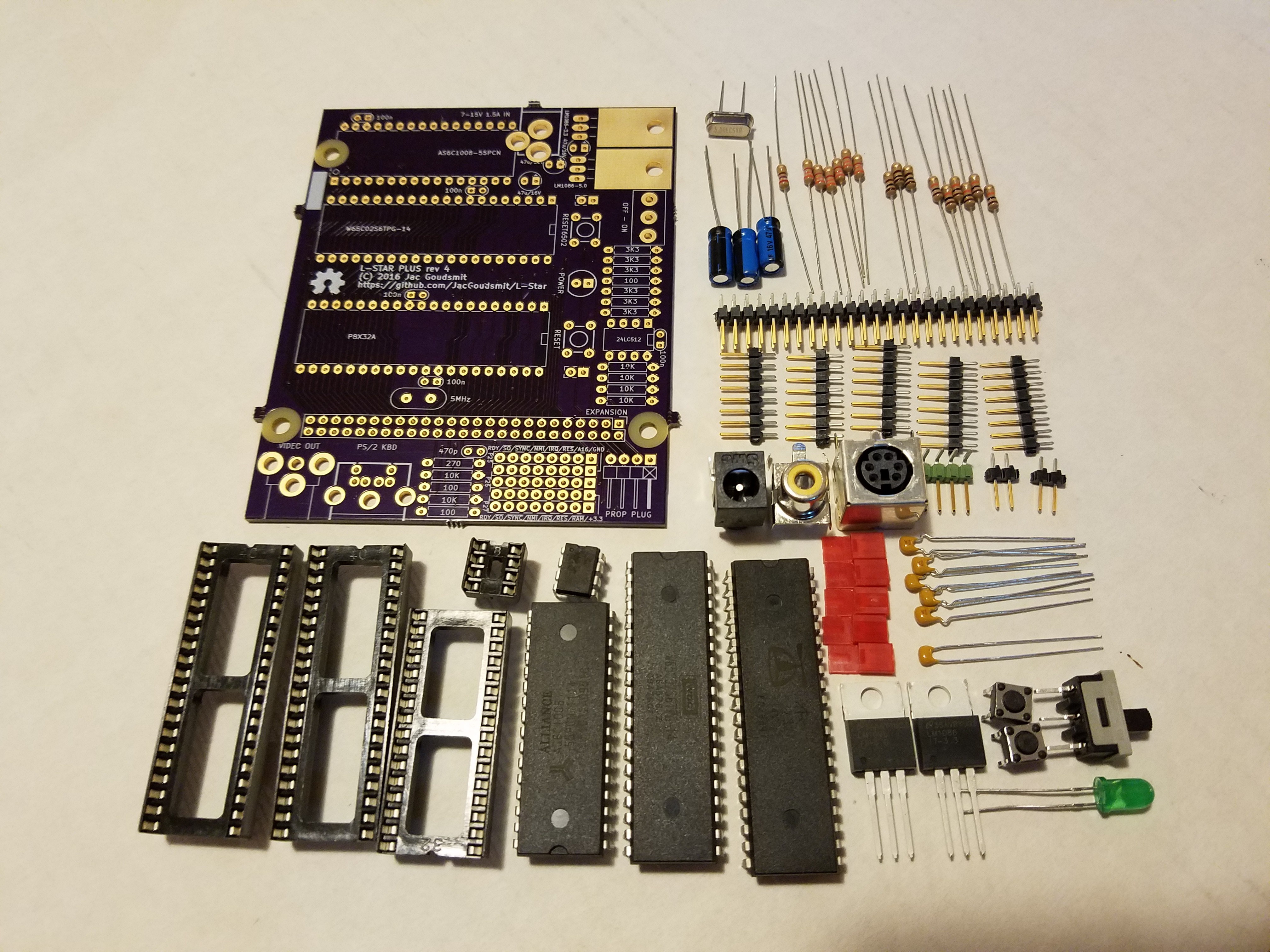
The first thing I did was to sort through the big box of parts that I had gotten from Mouser earlier in the week, with enough passive parts for 10 kits and then some. I decided not to get all the chips because I still have most of the chips from the first production run of #Propeddle: Software-Defined 6502 Computer and I could easily reuse those chips even though they're a few years old. They've been on conductive foam all that time so they should be fine. I figured it might be a better idea to invest a little bit into some extra passive parts so that I could get them at a lower price. For example, resistors get a lot cheaper per part, if you buy 200 of them instead of, say, 10 or 60.
Board 400
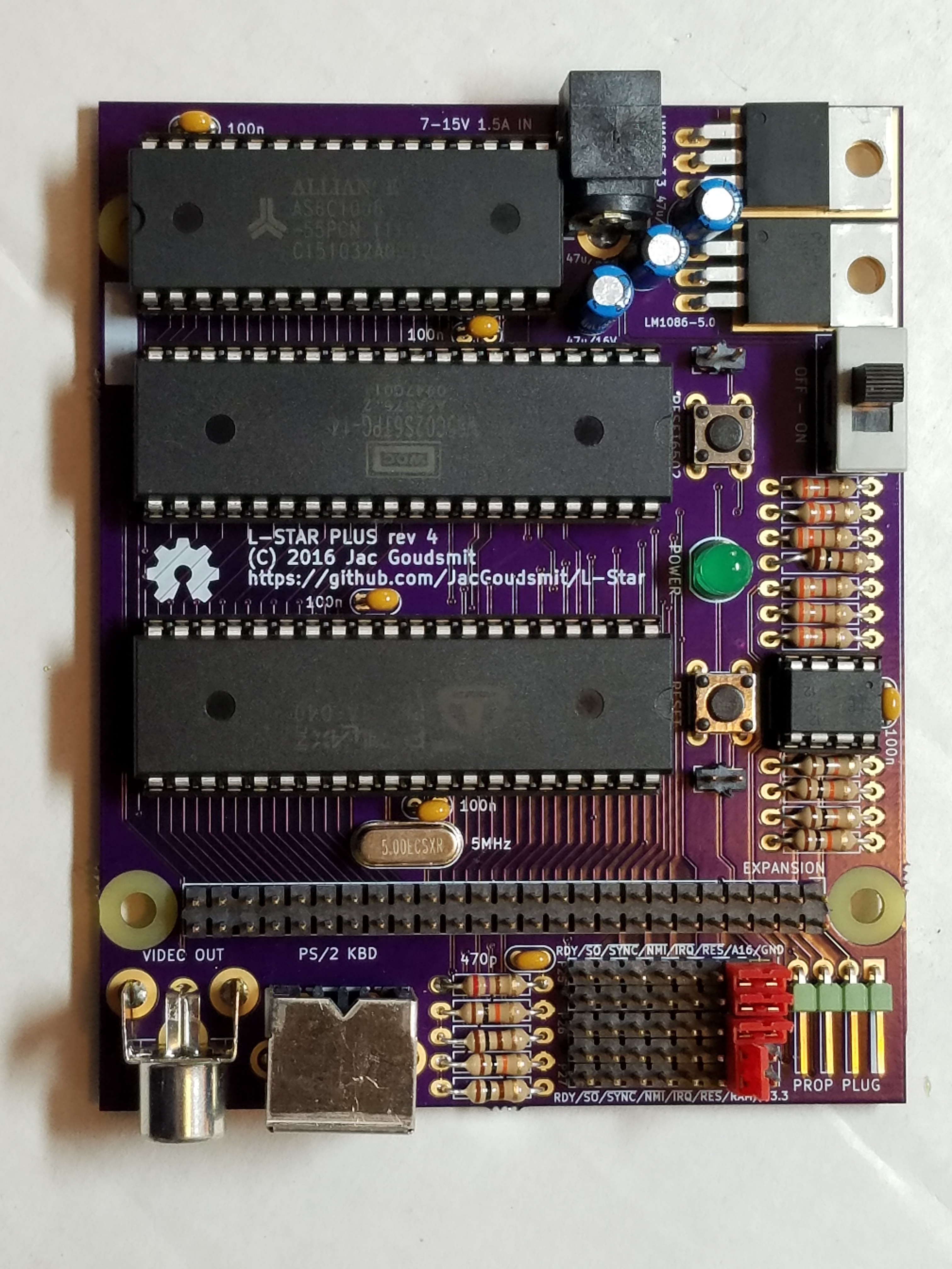
I've soldered so many different versions of my own project that I can almost do it in my sleep now. Well... That's an exaggeration of course, but the actual assembly of the first board which I will call Board 400, went pretty fast. I found a couple of minor problems that I'll fix for the production version (for example, now that the board is so much smaller as when I started, some parts are really too close together so I'm going to have to move some things around to make it easy to solder for beginners). But nothing was obviously wrong. I went through the entire assembly in one go and took pictures along the way that I might use for the building instructions, but I didn't really test anything along the way. You can probably guess where this story is going, right?
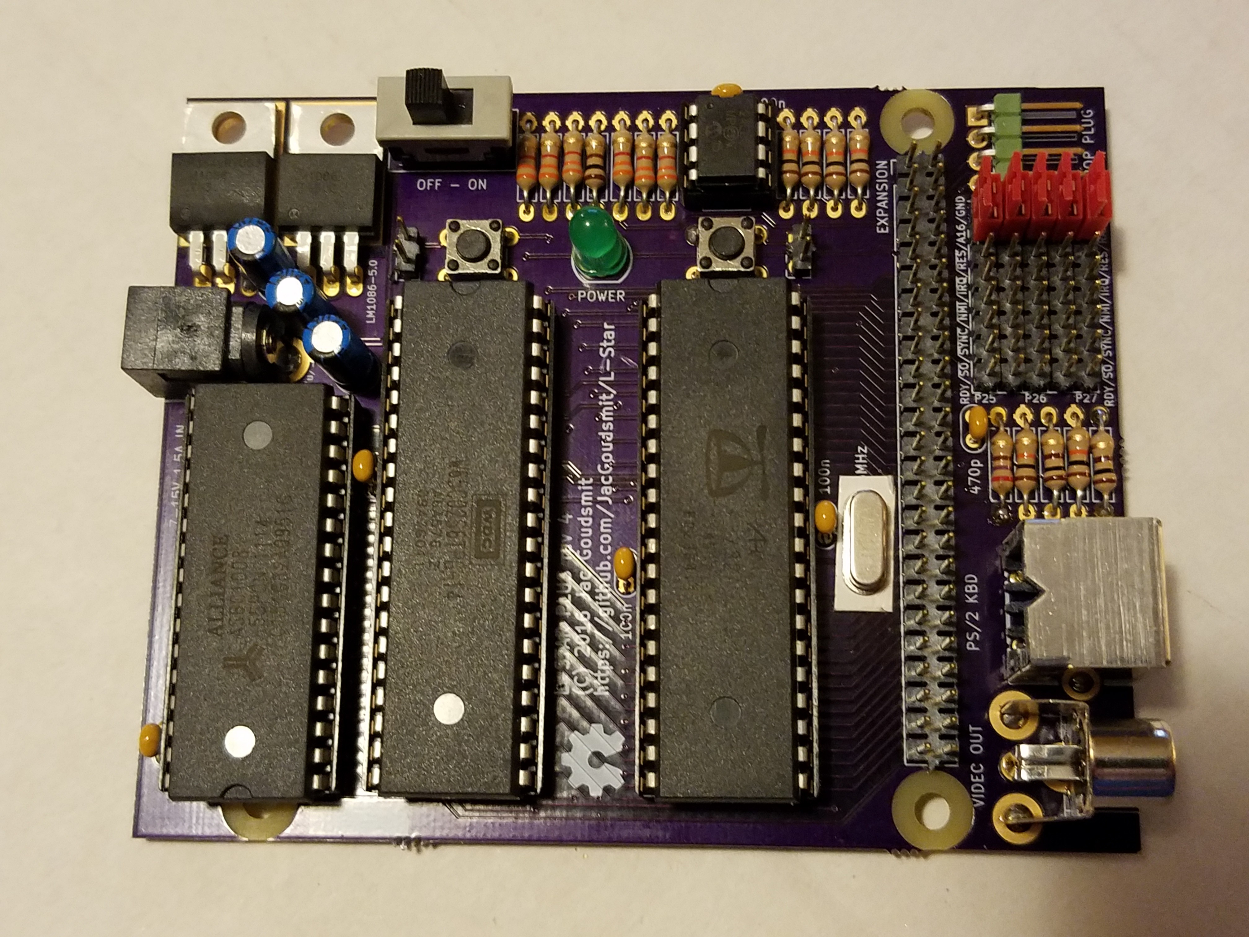
The board looks beautiful, and though things get crowded in a few places (which I will fix for the production version, as I said), it was easy to solder. But when I plugged it in... nothing happened.
As it turned out, there was a short between 3.3V and GND (the flood planes on the top and bottom side). This was the first time that that ever happened with any board from @oshpark. I've always gotten excellent quality PCB's from them and this was no exception. There was no short on the unpopulated boards. So what went wrong?
I started desoldering some of the parts from the first board (particularly, the ones that I noticed were close to other parts) to see if I had been too sloppy with my soldering. But the short didn't go away. Bummer! I went to bed and figured I'd look at it again on Saturday morning.
I had a closer look on Saturday but I didn't get any wiser from it. My 20 year old solder tin that I brought with me from Europe when I emigrated, sprayed rosin core everywhere of course, so I cleaned it up a bit to see if I could see any tin where there shouldn't be any. I didn't.
Board 401
So I sort of gave up on "board 400" and decided to solder together "board 401". I started with the resistors, and the MLCC capacitors. Then just for giggles I put my multimeter on the board. This one was shorted out too! What the actual beep?
I desoldered the capacitors from board 401 because it was easy to do, and measured again. Still shorted. I used solder wick and a solder sucker to clean the pads. Still shorted.
Board 402
I gave up on board 401 and started putting together board 402. I didn't really want to put all those boards together; as much fun as it is to solder them together, I really don't need that many L-Stars laying around my house! And if I was going to put all my own kits together for myself, I wasn't going to get paid for the parts. The passive components alone are probably close to $25 per board, and that's after I switched to the cheap header-by-the-mile parts instead of the cool green headers that I had before (which I will probably switch back to).
I started board 402 with the LED and the power supply, so I could quickly plug it in after soldering each part. But I didn't run into any problems at all, this one was just perfect and super easy.
Back to Board 401
Meanwhile, I had posted my non-progress on Google+ and got an email from Laen at OSHPark. He said he noticed the clearance around the solder mask was a little on the high side.
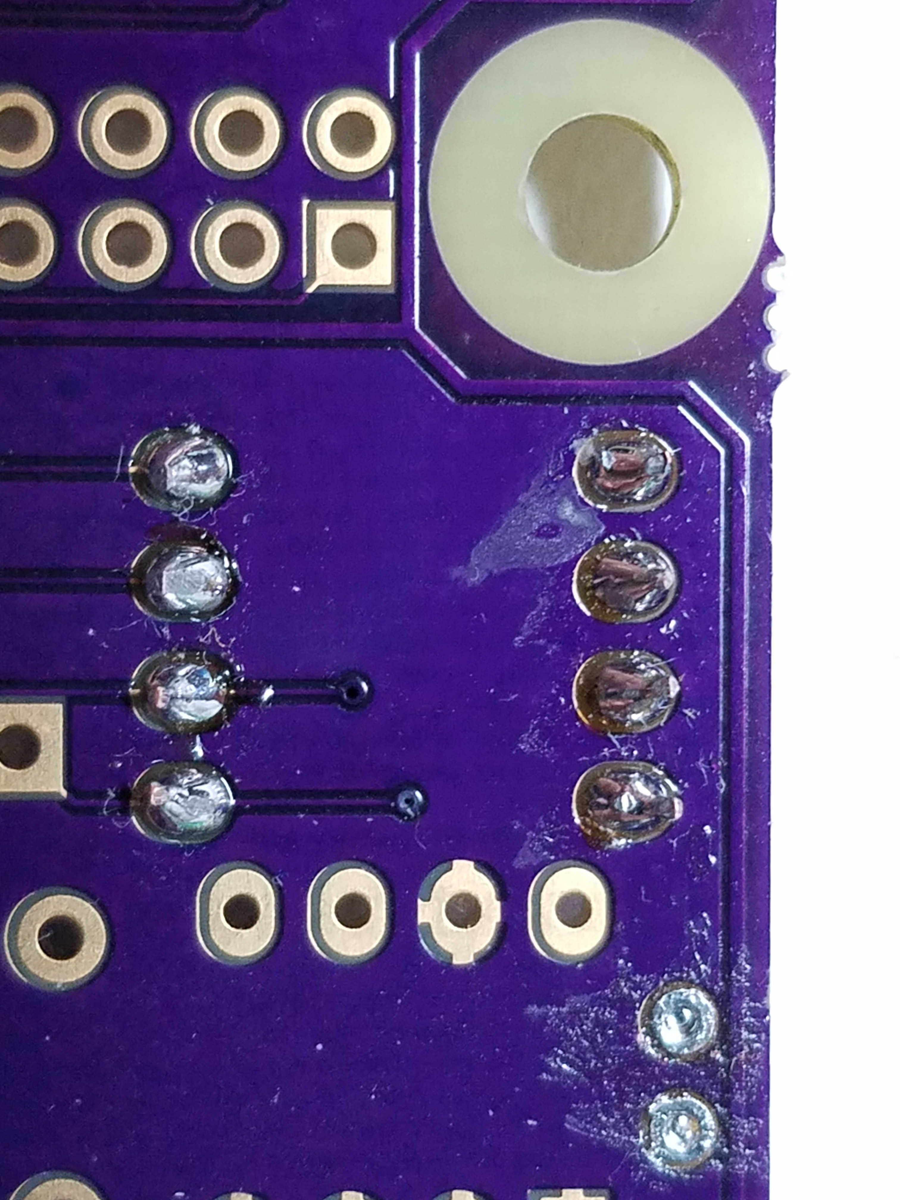
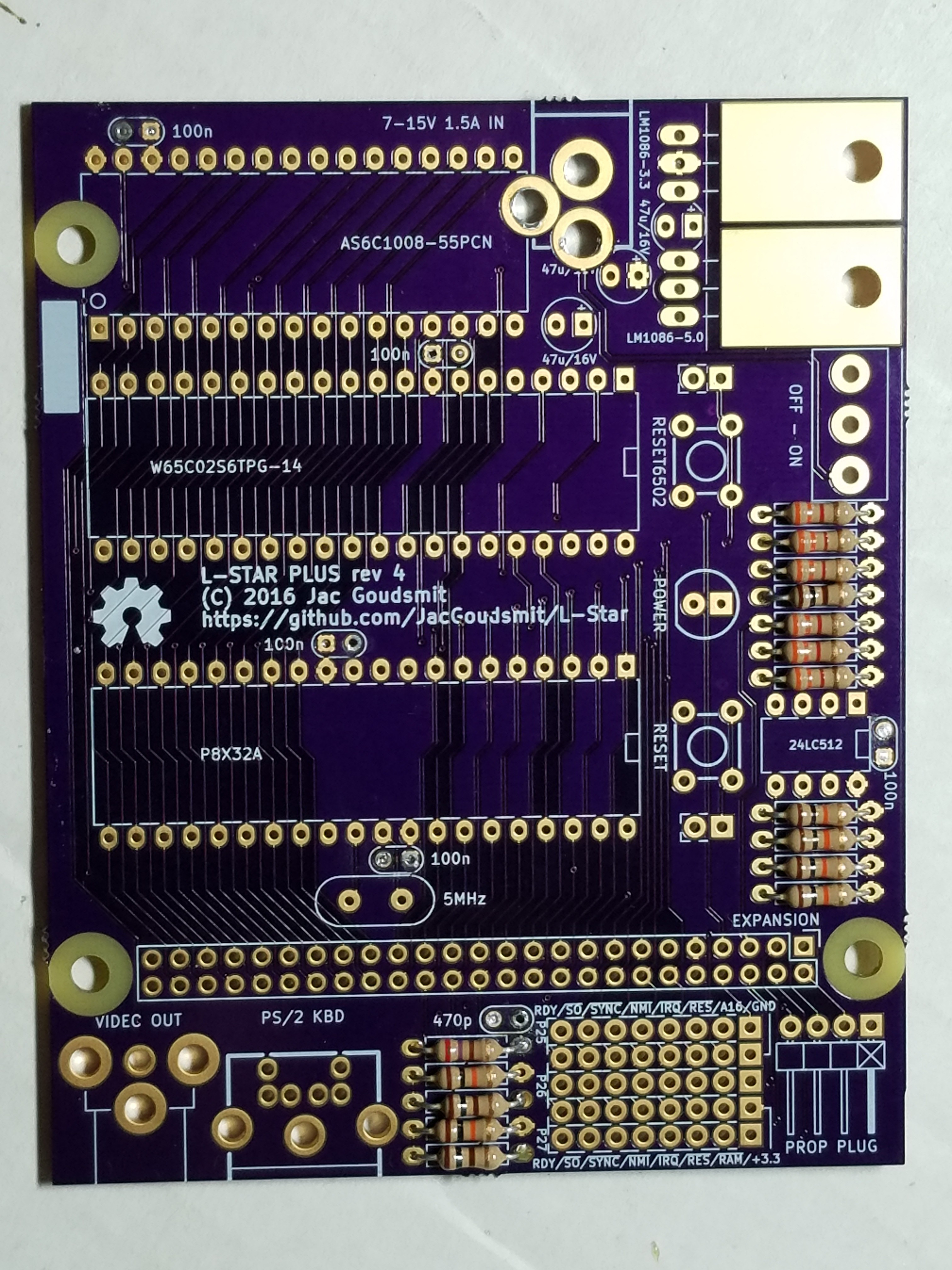
A close-up photo of board 401 reveals what the problem really was. When you look at the board with normal, say 49 year old eyes, you might think those shiny things at the edges of the solder islands are just like the the light reflecting off the edge of the solder resist near the edge of the board, but they are exposed copper from the GND flood plane. I must have played with the settings at one point and set the pad-to-solder-resist to 0.2mm (almost 0.008 inches) instead of 2 mils (0.002 inches). I bet I shorted out almost all those resistors I soldered in. To paraphrase captain Kirk: Face, the palmed front here.
I decided maybe board 401 would be salvageable, now I knew what the problem was. I cleaned up all the islands (which took hours!) and finally cleared the short circuit. Then I did the same as with board 402: I mounted the LED and power supply first, and then added each component with a quick light-up test in between. I caused (and fixed) a few more shorts but when I was done, I decided this would do as a demo model or something. I would have to put a sticker on the back side to remind me never to do any soldering on it, lest it would short out again. And that's when Murphy struck again.
Murphy's last laugh
I soon found out that, though I had avoided shorting out the flood planes (or anything else), there were a few points on the board that weren't connected even though they should be. For example, I could communicate with the Propeller but I couldn't store the program into the EEPROM. Strange. I tried another EEPROM that worked fine on board 402... Bupkis.
So I pulled out the beeping multimeter again and found out one of the I2C wires wasn't connected. I put on a botch wire to fix it, thinking nothing of it. No big deal, "Chips happen" as they say. But then I needed another one, and another, and another. The entire data bus except for one bit was disconnected between the Propeller and the 65C02. Can you see why, in the next picture?
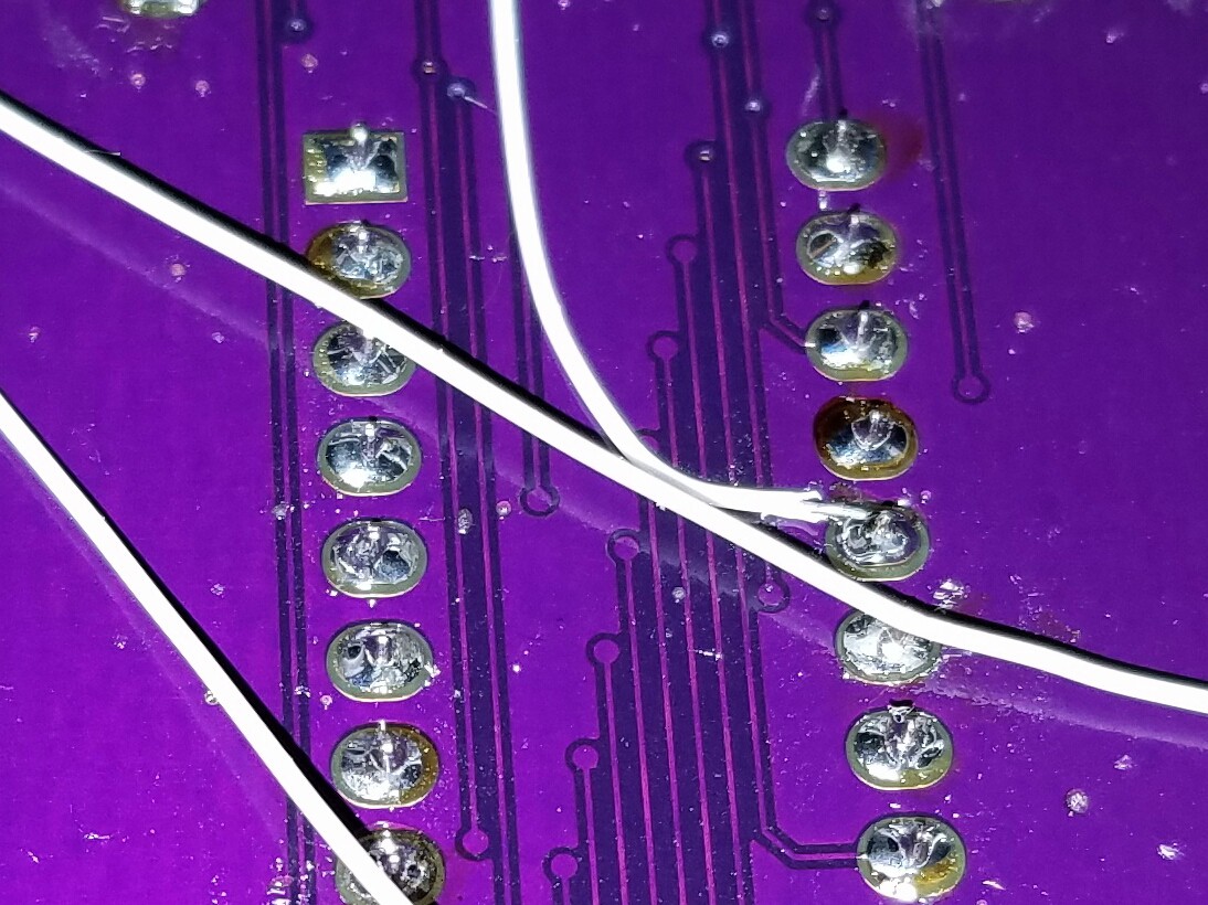
No, it's not because of my (I admit, utterly shoddy) soldering; it's because most of those vias don't have a hole in them, so they're not vias at all, they're just islands. The tiny drill that the board house used to drill vias, must have broken in the middle of my board, and nobody noticed it.
Conclusion
So yeah. About $60 in parts lost, as well as two OSHPark PCB's and pretty much a whole weekend. Lessons learned:
- Figure out exactly what the best settings are for clearance (pad-to-pad and pad-to-solder-resist)
- Don't use the most extreme settings that your PCB provider offers, unless you have to (I bet 0.015 inch drills break a lot).
- Solder accurately even if you've done the same thing 20 times already
And uh... suggestions on better solder tin are welcome, solder tin donations even more :-)
===Jac
Discussions
Become a Hackaday.io Member
Create an account to leave a comment. Already have an account? Log In.
Great writeup but a sad story
Are you sure? yes | no