Close
0%
0%

Battery ( Li-Ion ) care

Save Lithium-Ion battery!

Similar projects worth following
Lithium-Ion battery are very common and useful, but they become dangerous if the voltage fall below the 2.5 V.

This - completely -hardware project take care about this problematic.

5 Volt boards compatible.
3.3 Volt boards coming soon....

Why the discharging process is so important for a Lithium-ion?

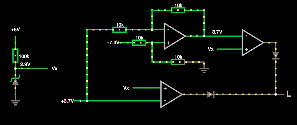
According to the discharge curve, the Li-Ion batteries has a maximum charge voltage ( 4.2 V ) and minimal discharge voltage ( 2.5V  but better 3V ).

For not over voltage the battery, we must yous a good Li-Ion battery charger, but for garantie the minimal discharge voltage we need a regulator.

On the market we can found a lot of device that can do it, but i want to create something useful, cheap and easy circuit for garantie the minimum safe voltage.

  • 1 × LM325N Power Management ICs / Linear Voltage Regulators and LDOs
  • 6 × Resistors E24
  • 2 × 1N4001 Discrete Semiconductors / Diodes and Rectifiers
  • 1 × battery 18650 Lithium-Ion

  • Zener diode in final form

    Dave02/10/2018 at 16:56 0 comments

    If you have seen my first schematic, we need to connect the 5v Board ( Arduino ) power pin for produce the Vcc for opamp and voltage divider.

    This is a little bit tricky for the connection, and i want to solve it.

    I introduce the new schematic with Zener Diode!

    You can play with this schematic at this link: http://tinyurl.com/ycsd9gva

    In this configuration we don't need the 5v from the board, but it use the voltage of the battery in series.

  • PCB beta format

    Dave01/30/2018 at 21:45 0 comments

    I added the header to help in the assembly.

  • Try the singles opamp

    Dave01/24/2018 at 21:29 0 comments

    It's time to put some wires and the opamps in the breadboard.

    For take it easy,  will use the 3.3 Volt on the Arduino as Vx.

    First comparator

    This comparator check the first battery.

    According to the complete schematic, is the battery connected is up to Vx ( in this case 3.3 Volt ) the led not turn on.

    So i connect the 1.5 volt AAA battery, an the result is: led ON.

    Now i connect the Li-Ion battery, 3.7 volt: led OFF.

    Differential component

    This opamp made the differentiam of the two inputs.

    In this case i used 5V and 3.3V . 

    The result is  5V- 3.3 V = 1.7 V ideal.

    Ok it's a good approximation.

  • Arduino sleep mode

    Dave01/21/2018 at 11:30 0 comments

    We have the electronic to control the battery discharge, but what happen when the battery hit the threshold?

    At the electronic level, the comparator rise up the output, but what will do the micro controlled attached to that comparator pin?

    The deep sleep mode, is a mode of all micro controller to get it in a very low power consumption. 

    In most of cases we use the Arduino micro controller, and it has some appropriate commands to jump in a deep sleep mode: https://goo.gl/VCsgSU

    I advise you to use this good library, Sleep_n0m1 : https://goo.gl/pH2Snf

    According with this library, i show you a simple example:

    #include <Sleep_n0m1.h>
    
    Sleep sleep;
    
    // attachInterrupt: https://goo.gl/DGR2bH for the single Arduino
    // for the ONE we only have the pins 2 and 3 attached to the interrupts
    #define intPin 2 // i use the pin 2
    
    void setup()
    {
    
      Serial.begin(9600);
      // attachInterrupt: https://goo.gl/DGR2bH
      // When the comparator go HIGH, the Arduino will go to the deep sleep mode
      attachInterrupt(digitalPinToInterrupt(intPin), deep_sleep, HIGH);
      
      delay(100); ////delays are just for serial print, without serial they can be removed
      Serial.println("The battery is ok.");
    
    }
    
    void loop()
    {
    // some interesting code
    }
    
    void deep_sleep() {
      Serial.print("Battery under 3V ! I'm going to sleep! Bye!");
      sleep.pwrDownMode(); //set sleep mode
    }

  • Circuit simulation

    Dave01/20/2018 at 15:51 0 comments

    First of all, i want to translate my schematic - by hands - to the Circuit Simulator.

    Link: https://goo.gl/LuN2R9

    Component & parts:

    • On the left we have a voltage divider, it produce the 3V output for the comparator.
    • The triangles are the Op Amp:
      • On the bottom and in the right up corner we has 2 Op Amp in comparator configuration.
      • In the center, we have an Ap Amp in differential configuration.
    • The 2 diodes in output at the comparators are there to avoid discharge current.

    When one of the two battery fall below the Vx voltage - here 3V - the comparator output, connected to that battery, rise up.

    If we connect the outputs of the diodes together at one of the Arduino's pin, we can advise the micro controller to jump in the deep sleep mode ( power off )  before damaging the batteries.

View all 5 project logs

Enjoy this project?

Share

Discussions

Similar Projects

Does this project spark your interest?

Become a member to follow this project and never miss any updates