 Ted Yapo
I know I shouldn't send this board out yet - always wait a day - but, I've just sent out three boards in as many days, and feel like I'm on a lucky streak :)
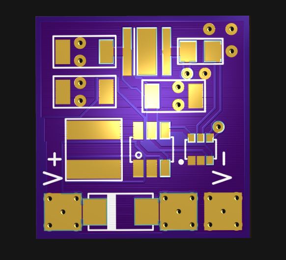
Then again, even with super-swift service, these boards are only $3.70. The PCB should fit inside a standard servo case with some room for a capacitor or two.
The circuit is a boost converter built around an MCP1624.
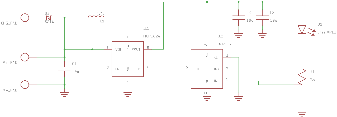
The MCP1624 will start at 0.65V, and once started will run down to 0.35V. Usually, the output is a fixed voltage determined by a resistive voltage divider into the feedback pin. In this case, I've substituted an INA199 current sense amplifier. This is basically a difference amplifier built around an auto-zero amp so it has a very low offset voltage. The gain is fixed at 50. With 10mA flowing through the 2.4-ohm sense resistor, there will be a 24mV drop. This is multiplied by 50 to get 1.2V, which is the feedback reference voltage for the MCP1624. If it all works, this should keep the current through the LED a constant 10mA.
The INA199 is specified down to 10mV full-scale drop across R1, which is impressive. I took care to use Kelvin connections to the sense resistor, which meant making a special resistor symbol and footprint in Eagle so the low-side sense trace didn't get absorbed into the ground plane. I used two overlapping SMD pads on each side of the resistor, and connected them to separate pins on the schematic. Eagle was a little finicky about it, but it seemed to work.
This arrangement allows a very small sense resistor to maintain high efficiency. With 2.6V across the LED at 10mA and 24mV across the resistor, the efficiency lost to the sense resistor is under 1%. Using a higher-valued sense resistor with the MCP1624 directly would cost more than 30%.
I have to be honest, I don't know how to evaluate the feedback stability of this combination. If it seems unstable, I'm going to whack it over the head with more capacitance. Hopefully, it just works.
I added an SS14 Schottky diode for charging the capacitor from the generator. I had intended to include a TL431 shunt regulator and a pair of resistors to clamp the supercapacitor voltage to 2.7V, but they didn't fit on the board. I can always wire a TO-92 version and a few 1/4W resistors free-form in the case.
If this circuit works, it could be interesting for driving LEDs from single 1.5V cells, too. A quick calculation has it running for more than a week from an AA alkaline cell, and probably longer from an AA LiFeS2 cell.
Wait, did I just re-invent the wheel? Is this just a solar garden light?
Discussions
Become a Hackaday.io Member
Create an account to leave a comment. Already have an account? Log In.