 The Big One
It has been a productive few days since the last log entry. But first for the magic smoke!
A week or so ago I plugged the ADC pin on my MCU directly into 12V Vout. There was some smoke, the smell of burnt chips... but the thing still apparently worked!
Or so I thought. On Tuesday evening it finally gave up the ghost, so I had to replace the 32u4 with another one which I (luckily) had available. Note to future self: triple check your inputs before plugging them into a MCU!
On a more positive note, I now have improved current limiting efficiency (thanks to Hacker404's suggestions). I am now using a PNP transistor instead of NPN, and the voltage drop from rails is only 0.7v as compared to 1.4v. This will let me get higher output voltages from lower inputs, which is good news all around.
The current limiting now gives a smooth curve down as it kicks in, rather than oscillating between fully on and fully off.
I have added support for an LED to show whether current limiting is enabled or not. (It is essentially just a 'high' signal, so you could hook it into a MCU or something if you wanted to do something more with it.... just be sure to step it down, as it is 12+V!)
Yesterday I successfully implemented and verified the DAC I2C address change message. (The DAC which I have chosen, the MCP4728, has a programmable address offset consisting of 3 bits. This is wonderful, but it means that you need to program them when putting the thing together.) With my latest code, this should be quite easy.
One problem that I am still encountering is completely turning off the output when current limiting is in effect. When testing, I noticed that I could not get any lower than 35mA output (at 12V), no matter what value I set the current limiting DAC to. I assumed it was just the PNP transistor leaking; however the phenomenon continued even when physically removing the current limit transistor! After tracing through the schematic, I found the source: the VSET op amp was supplying 35mA of current, which was traveling through the 200Ω resistor and the protection diode to the output.
I am not sure how best to solve this problem. The obvious answer would be to increase the resistance in the output path. Initial experiments show that this won't work properly, though, as adjusting the resistance makes controlling the LM317 very difficult. Other options would include using a shunt transistor to reduce the VSET voltage when current limiting is in effect (doable, but I would like to avoid the use of an extra transistor if possible). A 'nuke it from orbit' approach would be to revert back to using an NPN transistor for the voltage regulator... this is doable (I had voltage regulation working initially with this approach), but I do like the smooth output of the 317. More time will be spent on this problem this evening.
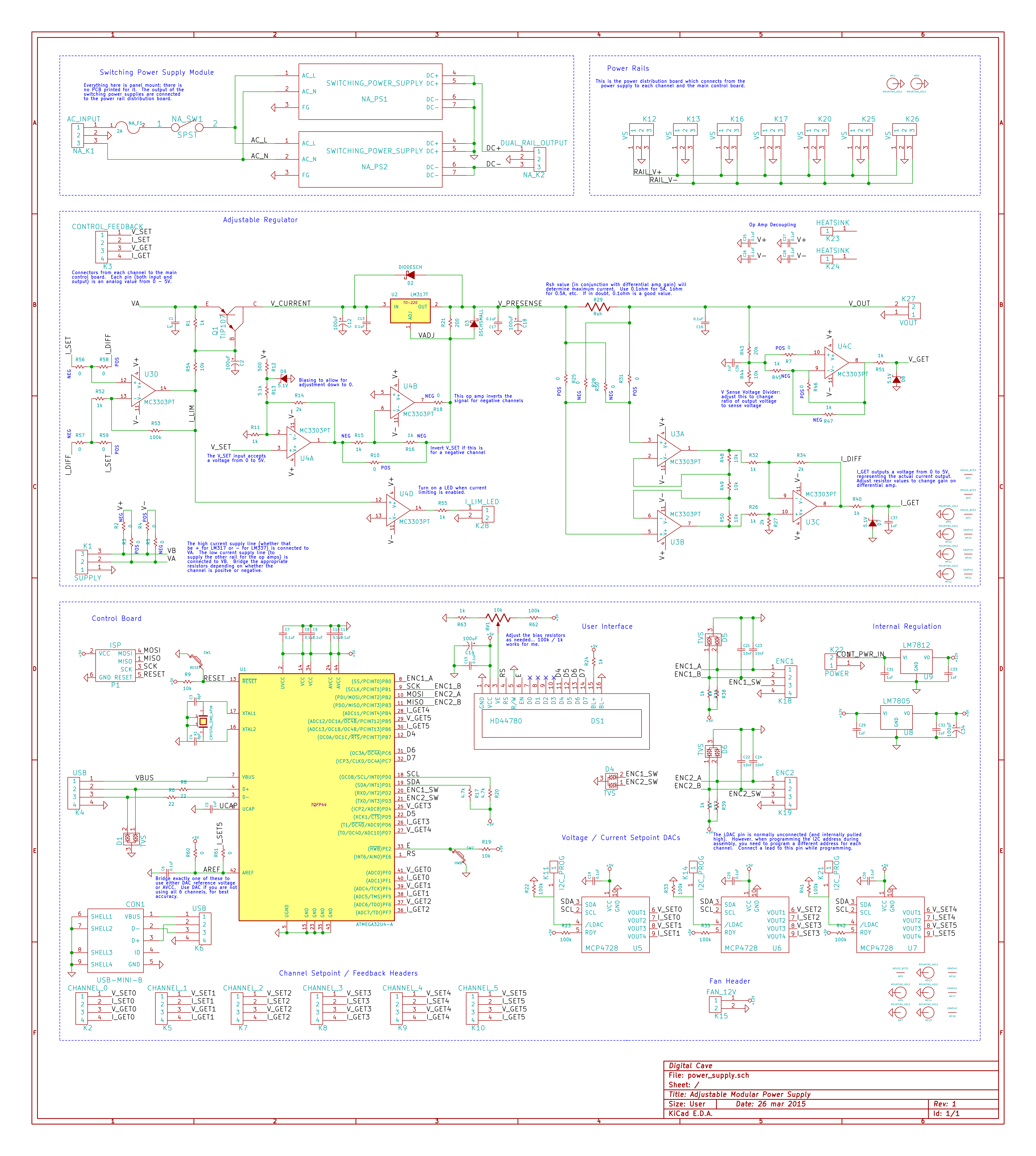
Finally, attached is my latest schematic. Enjoy!
Discussions
Become a Hackaday.io Member
Create an account to leave a comment. Already have an account? Log In.