 Kert
KertSo ... everything has some kind of start as does this project. For a start there was an idea to do a custom PC chassis out of 2 mm aluminium: http://www.overclock.net/t/1533039/scratch-build-axon-stretcher/0_50#post_23516587 I got it all figured out including assembly in autocad inventor nd exported flat patterns for laser cutting.
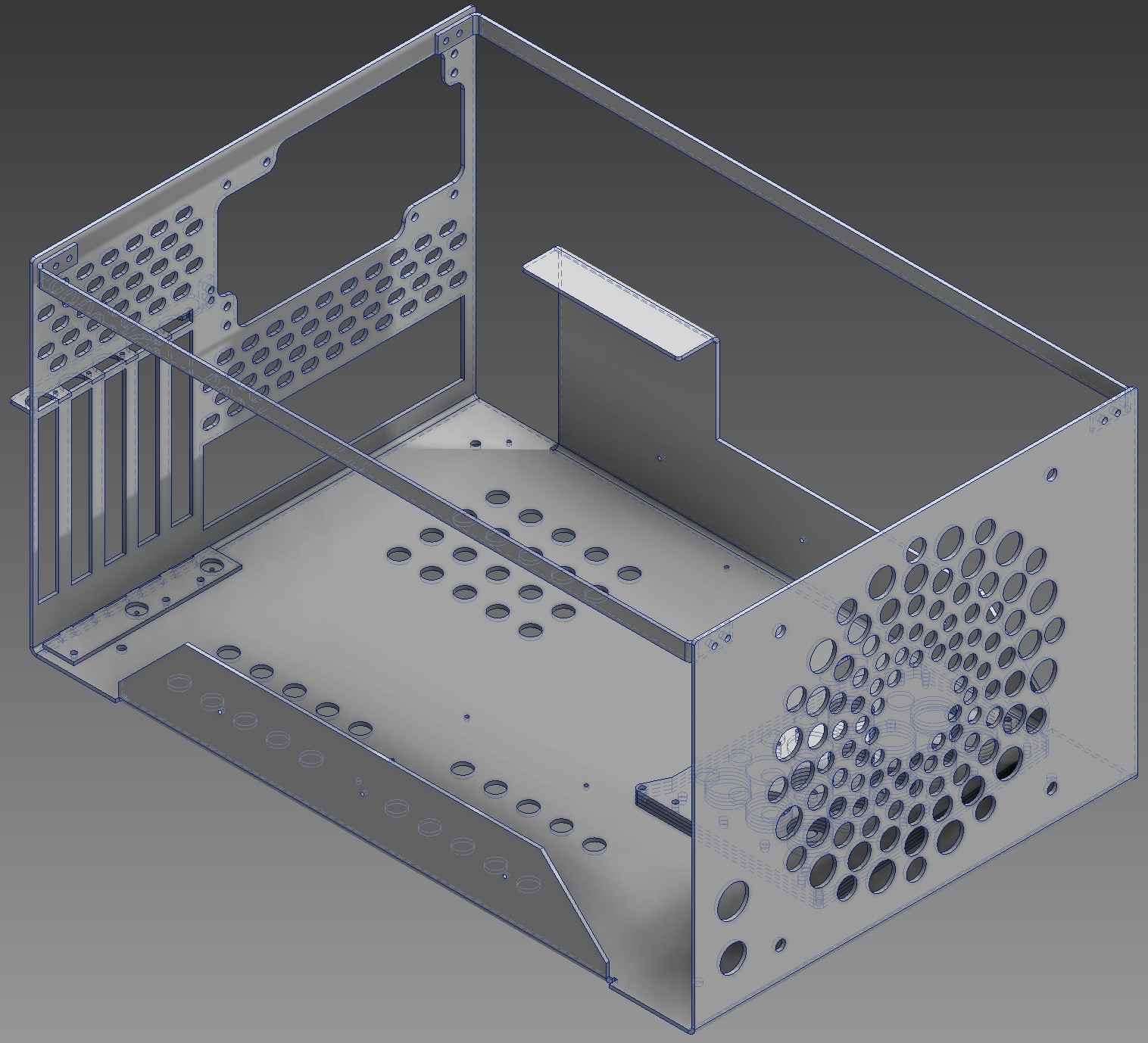

And then ... well then I got a price quote from one of the local metal shops with 4 kW laser after poking at companies not really interested in doing it for me for half a month. The price was fair, I would say, but way above what I expected. With all the taxes added in about 225 EUR for cutting less than one square meter of 2mm thick aluminium (about 28 meters of cut line) and twelve 90 degree bends. Out of that about 30 EUR is the material cost.
But by that time I was already thinking something on the lines of "if I would only have the cnc machine myself in my basement". I had been bouncing about the idea at that point for few weeks, doing the reading up on the stuff on what little free time I had in my life after little daughter, wife and work had taken their toll. The price quote ballpark was about the same as I had estimated very roughly the cost of cheaper end electronic components and cheapest seemingly reasonable enough bearings, leadscrews or belts, etc. to be. I thought about it for a week and then decided to put the PC case project on hold for a little while and delicate what free time I have to making a hobby CNC machine for myself. I expect to get somewhere within a year or so so it is not going to be a fast project by any means.
For a start I did a spreadsheet with several options for comparing them:
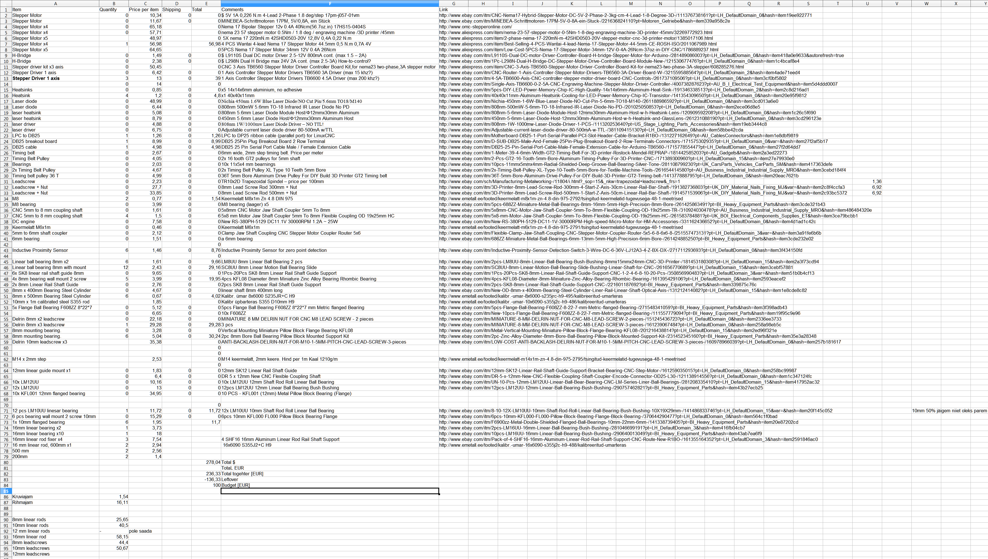
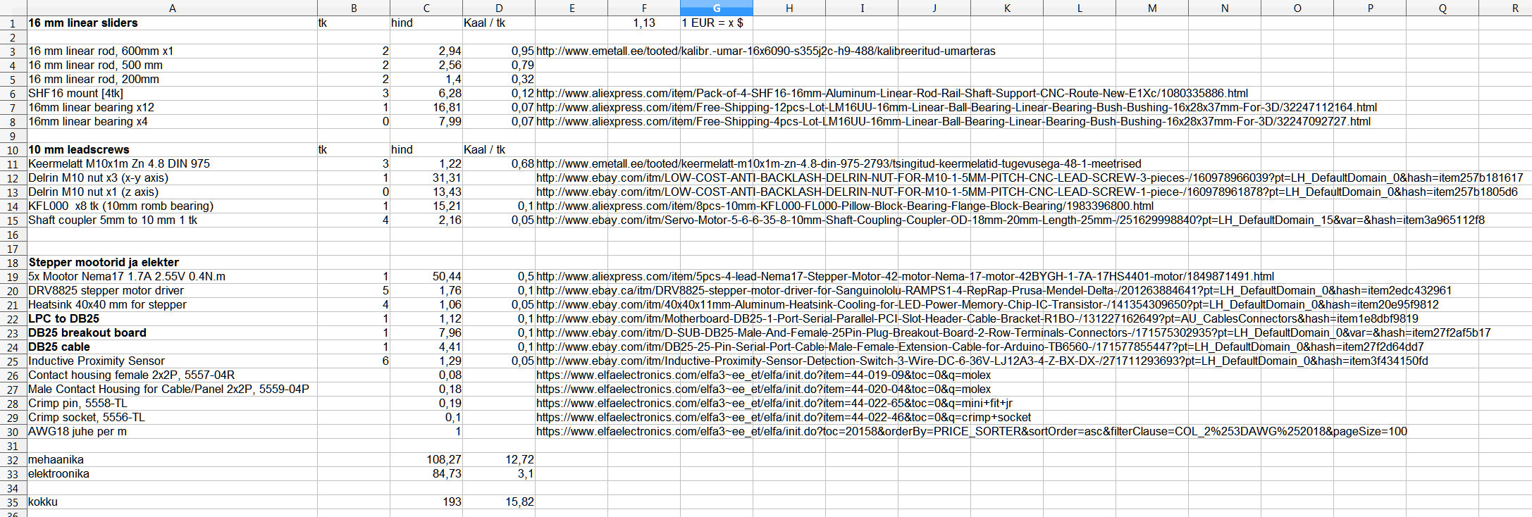
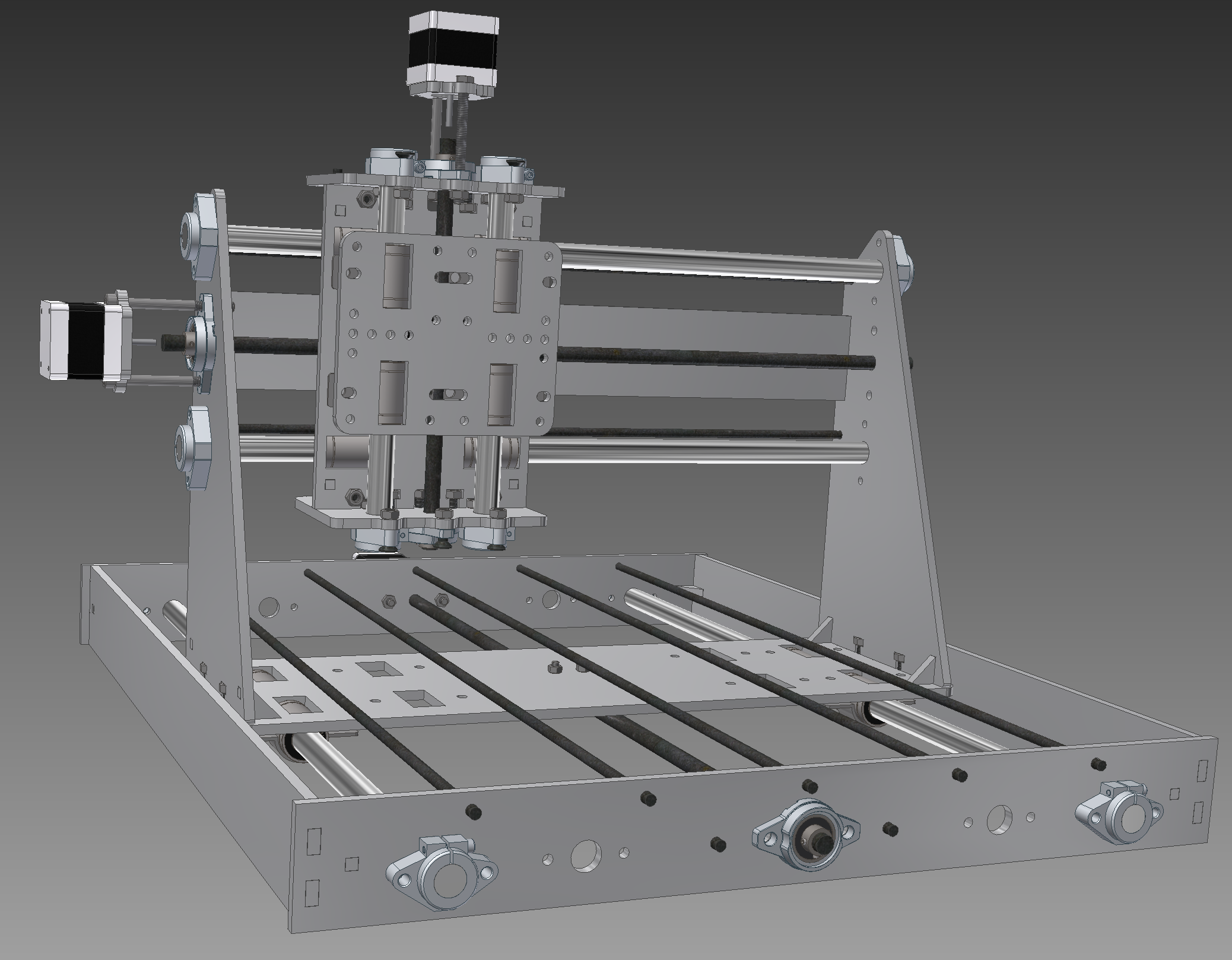
16mm calibrated linear rods (available from one of the local shops at reasonable price) and 16 mm linear bearings. At first I debated between 8 mm and 12 mm but 12 mm calibrated rod is not available in here and all things considered the 16mm was the next option. I am going to get only the bearings without the brackets to hold them as these are sort of .. well .. expensive and will have to jury rig something together for holding them. Currently thinking of just using 28 mm Inner diamater pipe clambers and a small opening in the underlying plate to fix them in place.
10 mm regular metric leadscrews. I did consider belts but regular metric leadscrew seems to be a bit cheaper option for me everything considered including cheapest possible deltrin anti backlash leadnuts from ebay. Although I must add that I do like a Core XY concept a lot http://www.corexy.com/corexyr1/index.html - it just was not as conservative with additional space and I'm not sure of rigidity of it for my porposes as I'm planning to use only 6mm thick material for chassis.
And then some electronics for the stepper motors and hooking up the PC. After some back and forth I decided to use DRV8825 based stepper drivers that are initially designed for arduiono but as far as I can see they should be also driveable from the parallel port of a PC with the linuxcnc without major issues. I have currently ordered a DB25 breakout board, one of these drivers and one cheap stepper motor to test the concept. These should arrive in about a month or so (free shipping from china, eh)
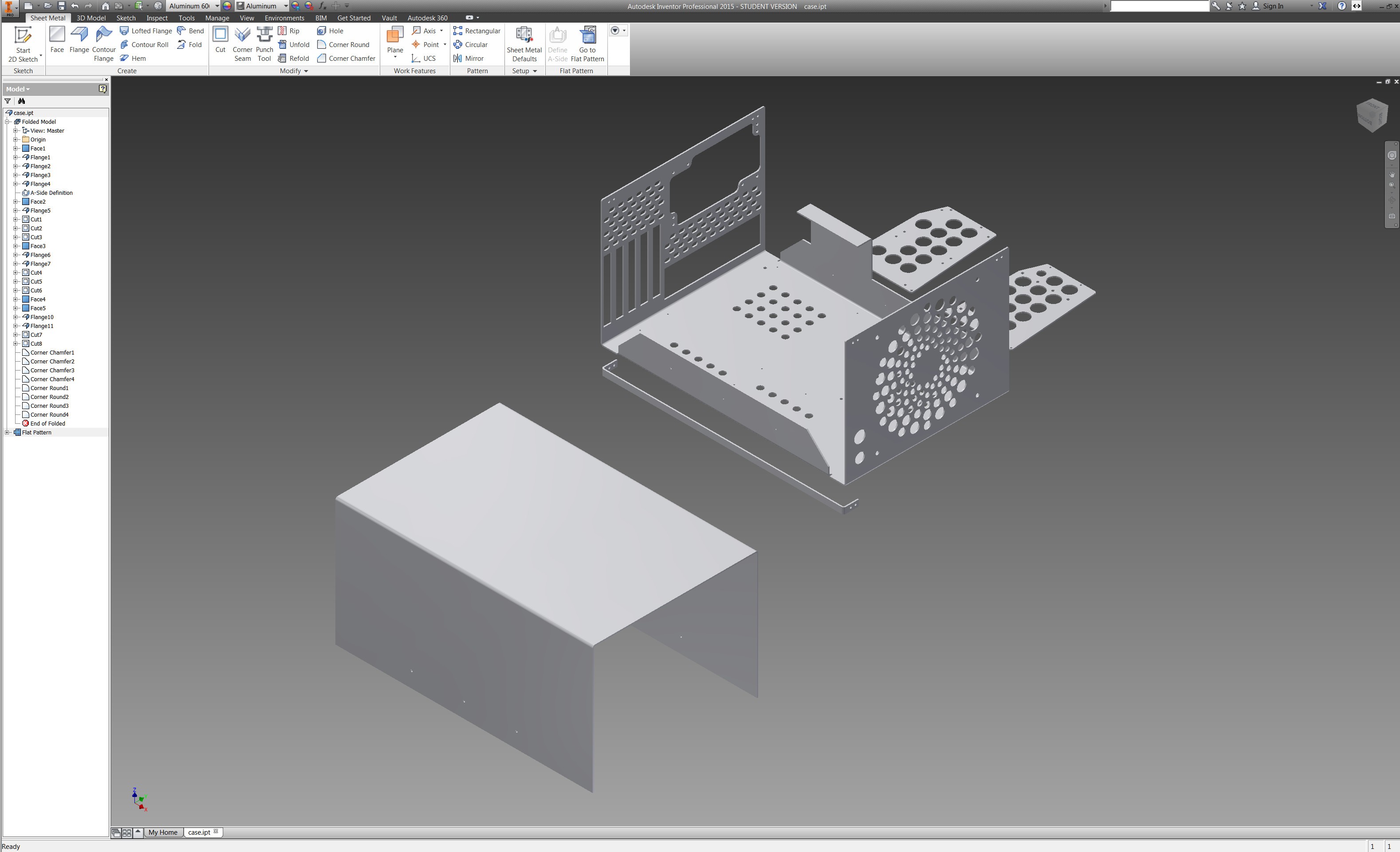
So now I am so far that I have figured stuff more or less out in autocad and done some assembly thinking in autodesk inventor.
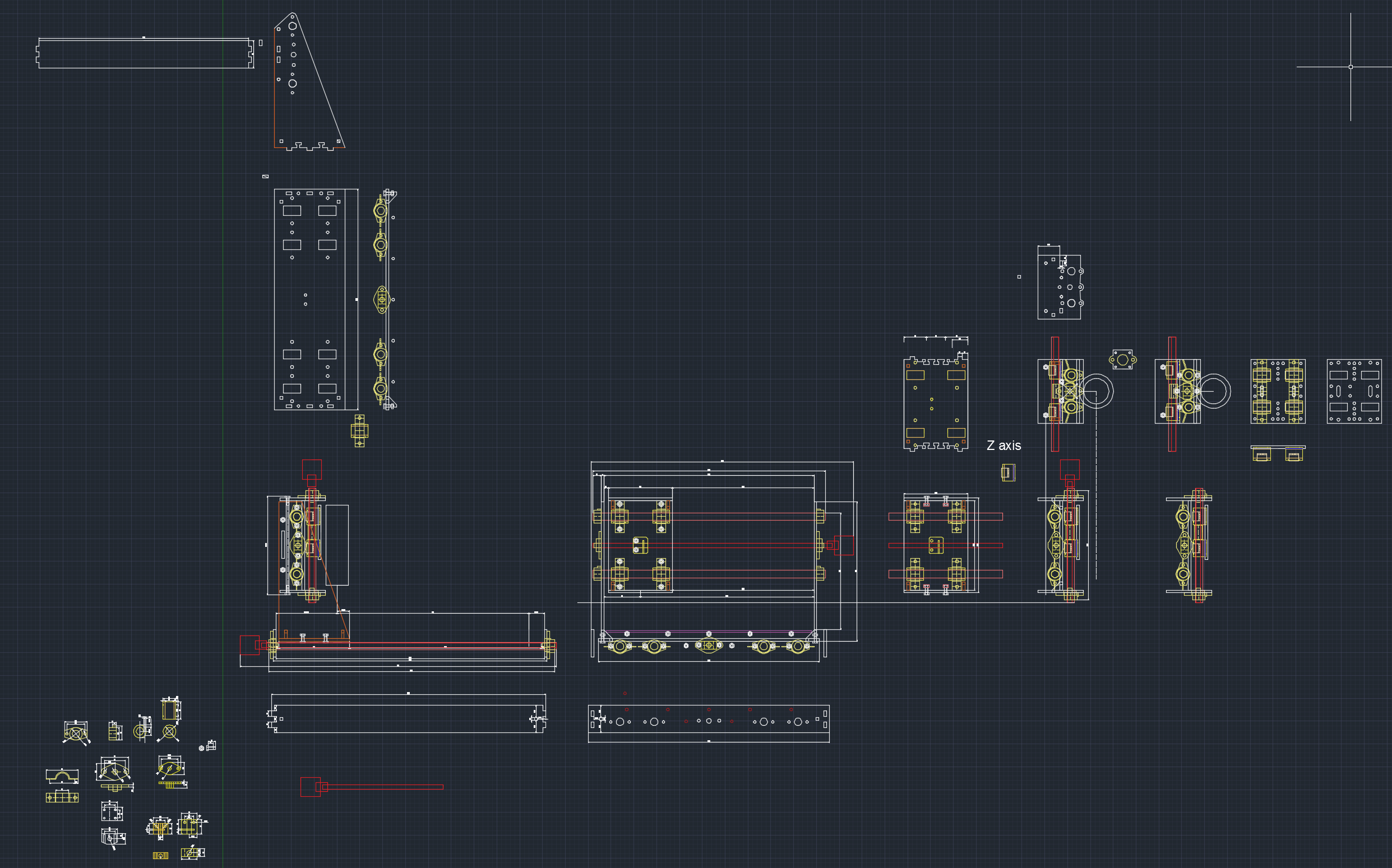
As far as the frame material goes. Initial design was for 6mm thick aluminium plate (as that is the thickest you can reasonably buy apparently around here without selling your kidney) - or steel - although as both would have to be cut by laser or waterjet the material price difference would end up to be ... neglible. Now lasercutting metal is expensive so when I go and get someone to do it I should be pretty damn sure it's 100% correct the first time around.
So I intend to do the very first test version in 6mm acrylic/plexi or acetal/pom to see that everything is ok in reality as well. I have observed that on paper (or in cad for that effect) one can do things that physical reality can object. And so far physical reality has always won that dispute as far as I am aware. Hopefully the first mockup, once I get everything assembled is at least somewhat useful already. Who knows, if I'm happy enough with it might even skip the 6mm aluminium part of the plan.
A number of components on that drawing have been taken from GrabCAD. Credit where credit is due:
https://grabcad.com/library/shf16-shaft-support-1
https://grabcad.com/library/16mm-linear-bearing-lmu16uu
Discussions
Become a Hackaday.io Member
Create an account to leave a comment. Already have an account? Log In.