 Bud Bennett
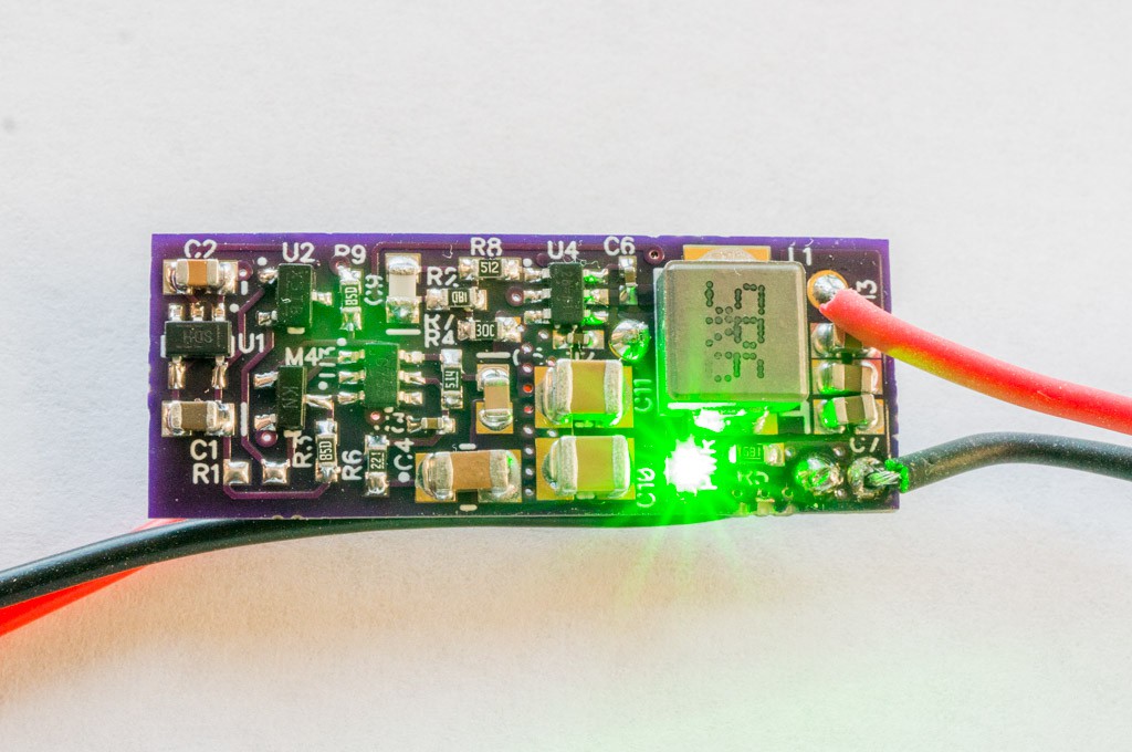
I've been traveling a bit the last few weeks and came home to a bunch of PCBs and a few components that finally arrived from China. I had to prioritize. The BEC version was a first pass effort, so that got the highest priority. I knew that the BEC was going to need a second pass to fix the input transient problem so i only assembled a single unit. It was larger than I expected. I got accustomed to dealing with very small boards and this one is huge by comparison.
Crappy Input Caps:
To keep my options open, I had ordered several ceramic SMD capacitors from Chinese eBay vendors that I hoped would work as input caps:
- 10µF 50V 1210 (no temp rating)
- 22µF 25V 1206 X7R (not really)
- 22uF 50V 1210 X7R (unbelievable!!!)
I tested the capacitance change vs. voltage and was disappointed with the result. The 10µF/50V caps decreased to less than 1µF @ 17V. The 22µF/25V measured <3µF at 10V. The only hope was the 22µF/50V, which measured 6µF @ 17V. I could have ordered some X7R 1210 from Digikey, but it was going to cost $3.00/each in my quantities -- not an option.
The Data:
I measured a few parameters to make sure that things were working:
- Off-state current draw was pretty good -- 7.7µA @6V increasing to 10.3µA @16.8V.
- On-state current maxed out at 14.2mA @ 16.8V.
- Line regulation is so-so: 5.05V @Vin=6V, to 5.17V @Vin=16.8V.
- Load regulation is hard to measure without an electronic load, but seems to be better than the line regulation.
I also measured input ripple voltage and output ripple voltage:
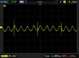
No Load Output Ripple Voltage:
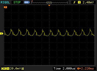
Output Ripple Voltage with 5A load:
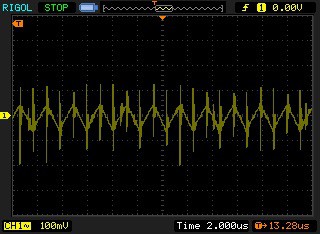
Input ripple voltage (Vin ~ 3S LiPo Battery):
This all looked pretty good. I decided to see what the input transient voltage waveform looked like for a couple of different battery types:
Input voltage transient for 2S LiPo battery:
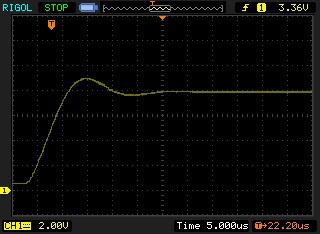
The battery had a resistance of about 100mΩ so the resulting transient doesn't ring much.
Input voltage transient for 3S LiPo battery:
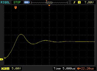
This 3S battery had a much lower internal resistance and there is a bit more ring as a result (And there was quite a bit of wire length between the battery and the board). Even so, the peak is about 17V, which is not a problem for the switching regulator (which has a 20V abs. max. input voltage rating). Though it is doubtful that the board will survive a 4S LiPo battery.
Load Tests:
I used a 22Ω 1W resistor for an easy load test. The BEC did not have a problem with this load and the output decreased only about 20mV over the entire input voltage range.
Things got more interesting when I attached a 1Ω/20W resistor to the output. The output voltage dropped to 4.97V and then steadily dropped over the next minute or so until the output voltage dropped below 4.9V where the buck converter hit its thermal limit and it began to disconnect the load to limit its junction temperature.
At this point I was pretty bummed out. It was obvious that the BEC was not capable of handling 5A as a continuous load. This result was not unexpected. I was boning up on thermal resistance and power dissipation of PCBs while traveling and had determined that a PCB this size could only handle about 0.5W of power dissipation to keep the junction temperature of the switcher IC less than 150°C.
So what load current was it capable of handling continuously? I kluged together three 4Ω resistors in parallel to yield a load resistance of 1.33Ω - 1.35Ω, which would draw 3.75A at Vout = 5V. When I connected this reduced load current the BEC was able to keep the output voltage steady at 4.95V until the battery dropped below 6.5V and the input voltage crashed pretty quickly. My calibrated thumb determined that the temperatures of the switcher and the power inductor was a bit higher than 50°C. I expect the temperatures to increase a bit when the board is covered with heat shrink so it is probably fair to call this design capable of 3A continuous load current, with bursts to 5A for less than 30 seconds.
I had recently purchased a couple of stand-alone BECs from a Chinese source that claimed 5A over 2S-6S voltages. I decided to connect one of those BECs to the same 1.33Ω load resistance to see how well it would perform. IT LASTED ONLY 10 SECONDS BEFORE GIVING UP. It went absolutely berserk!. My voltmeter could not display a voltage so I don't really know what happened. That made me feel better. I changed the load resistor to 2.5Ω and the Chinese BEC was able to keep the output voltage steady at around 4.9V, but the board temperature got too hot to handle ( it is probably a non-synchronous design).
General Conclusions:
This design will supply a 3A continuous load current, with 5A short duration bursts, over a voltage range of 6V < Vin < 13V. Is that good enough? Perhaps some real work application and field testing is in order.
Up Next:
- Order 2nd pass MagSwBEC PCBs that might function with 4S LiPo batteries. The updated schematic is in the project details section.
- Test results of the 30A mag switch second pass.
Discussions
Become a Hackaday.io Member
Create an account to leave a comment. Already have an account? Log In.