 Bud Bennett
2018-02-05:
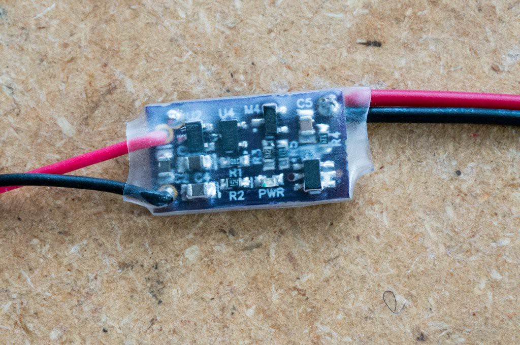
I received 3 PCBs from OSH Park today. Got them populated pretty quickly. In the cursory tests that I have performed they appear to work as intended. This pass did not have the 10 second memory hold feature, but included all of the other functionality. Here's the assembled board:
I attached some JST connectors to the input and output. I then hooked up a BEC (Battery Eliminator Circuit) to the output, which then fed a servo tester set to automatically swing the servo back and forth to its limits, and then connected a small 9g servo to the output of the servo tester. Here's a video of the operation of the circuit (if this link works):
https://drive.google.com/open?id=1kF2ffSATZuE9BW8aoX17dy0tuc_bvvuK
I also measured off-state current to be around 15µA. The meter was bouncing around a lot -- I think due to the sampling nature of the hall-effect switch. That is good enough, given the unknowns in some some components.
2018-02-07:
The on/off function is working nearly perfectly so I depopulated C4 from the board and it still works perfectly. C4 was there to prevent unwanted fast glitching if the Hall-effect switch generated more than one clock pulse when the magnet was applied. There is quite a bit of hysteresis in the Hall-effect switch and noise doesn't appear to be a problem.
The range of the magnet that I'm using (a stack of 2 - 8mm diameter x 1mm thick neodymium) is about 1/2", which is just about perfect.
I've tested the operating voltage range up to 13V, and it still operates the LED down to 2.25V.
Load Current Test: I attached a 2Ω 10W load resistor to the output and a 8V LiPo battery to the input. When I turned the switch on the battery voltage dropped to 7.5V and I measured 52mV from B- to OUT-. This yields an on-resistance of 13.3mΩ for the 3 FETs in parallel. The power dissipation in the output switches is less than 200mW when the switch is supplying 28W to the load. That's pretty good! That 200mW is spread across the three FET switches and they will have no trouble dealing with that relatively small dissipation. The board did not get very hot during the test, but the resistor was too hot to touch.
I think I'm done with testing this version. Time to think about any other changes to the design (other than removing C4) to implement in the second pass design.
Discussions
Become a Hackaday.io Member
Create an account to leave a comment. Already have an account? Log In.