Even though i thought of a different way to control the chip involving a digital Potentiometer ( going to prototype later), I found that that you can control the chip by feeding the feed back pin directly.
The set up follows the provided buck schematic from the datasheet except the feed back pin is hooked up directly to a signal generator. ( I forget to take a picture of the setup.)
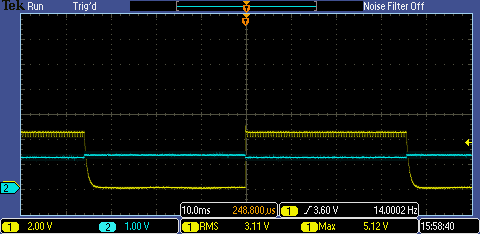
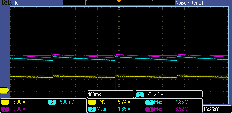
I feed the chip with a square wave with a high voltage of 1.3 an a low voltage of 1.2. In other words , a .05 volt square wave with a dc offset of 1.25 volts.
Blue is the Signal generator
Yellow is the output of the chip
(Note: Chip only, with a 200 Pf cap, No inductor )
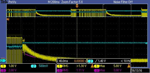
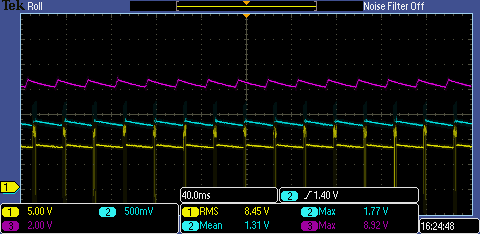
Same channel setup , purple is voltage output in buck mode. Now the chip behaves a bit different. The decay curves after the feedback goes high remind me of discharge curve of a capacitor. I don't have any clue to why the chip does this.
(Note: Now includes inductor)
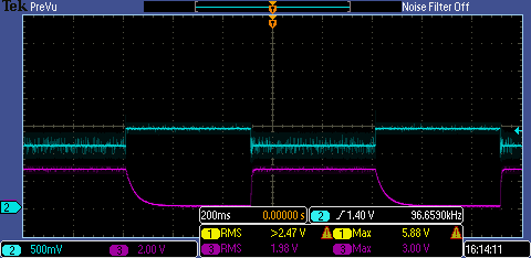
Here's another picture, only with the signal gen and the output.
When I finished, I decided to set the chip up exactly like in the example in the datasheet, with some components substituted, namely the inductor.
(NOTE: I did not use a load resistor.)
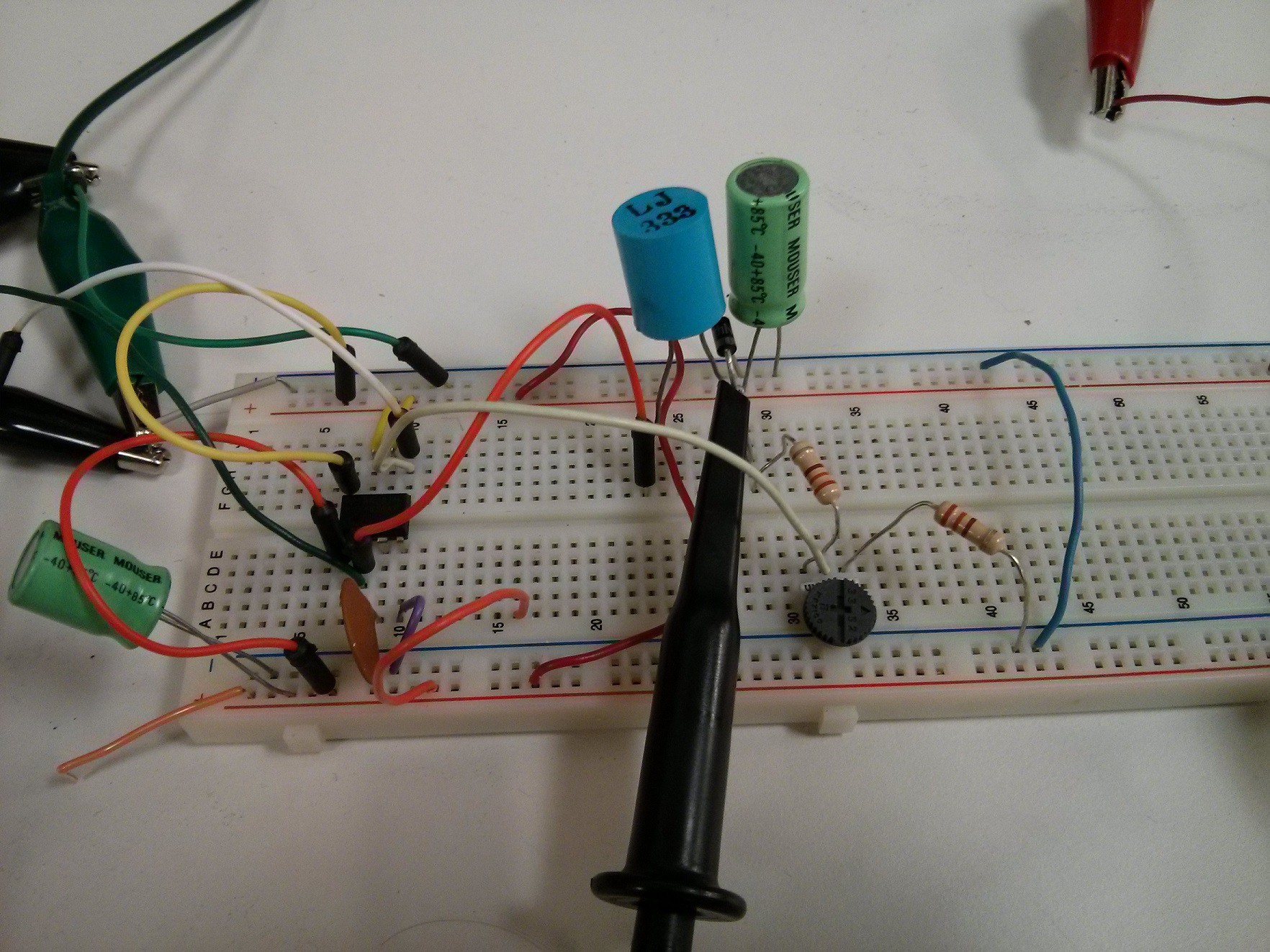
I took two snapshots of it in action.
Discussions
Become a Hackaday.io Member
Create an account to leave a comment. Already have an account? Log In.