 Pinski1
My goal for this project was to improve the exposure of PocketQube femto-satellites. These are 50mm x 50mm x 50mm satellites that have been very popular in the news for their extremely low cost to orbit. I want to add to the open source QubeCast Max transmitter/receiver board with another core board that is critical for a PocketQube, the Electronic Power System (EPS). Without an EPS board you cannot generate power to keep your satellite transmitting or carrying out the science that you intend.
Small satellites were born as a result of an over all industry trend to increase the reliability and longevity of satellites as they cannot be repaired. This lead to larger more expensive satellites that cost more to design, manufacture and launch into space. The increase in costs also meant an increase in the required reliability which mean only parts which had already been flown or proven to work in space could be used in the design and manufacture. This cycle would keep going increasing the cost which would increase the required reliability all to the detriment of innovation. To counteract this small satellites were born, design smaller satellites with shorter lifetimes and thus less required reliability which makes them cheaper to design manufacture and build. They're also cheaper to launch as they could be auxilary payloads on larger satellite launches. The most popular form-factor for these now is the Cube Satellite which is 100mm on each side.
To continue the cycle PocketQube was born in 2009 in the US as a way of reducing the costs even further down to where most universities could feasibly build, test and launch one. You can read more about them on their Wikipedia page here.
The block diagram below shows a typical PocketQube satellite.
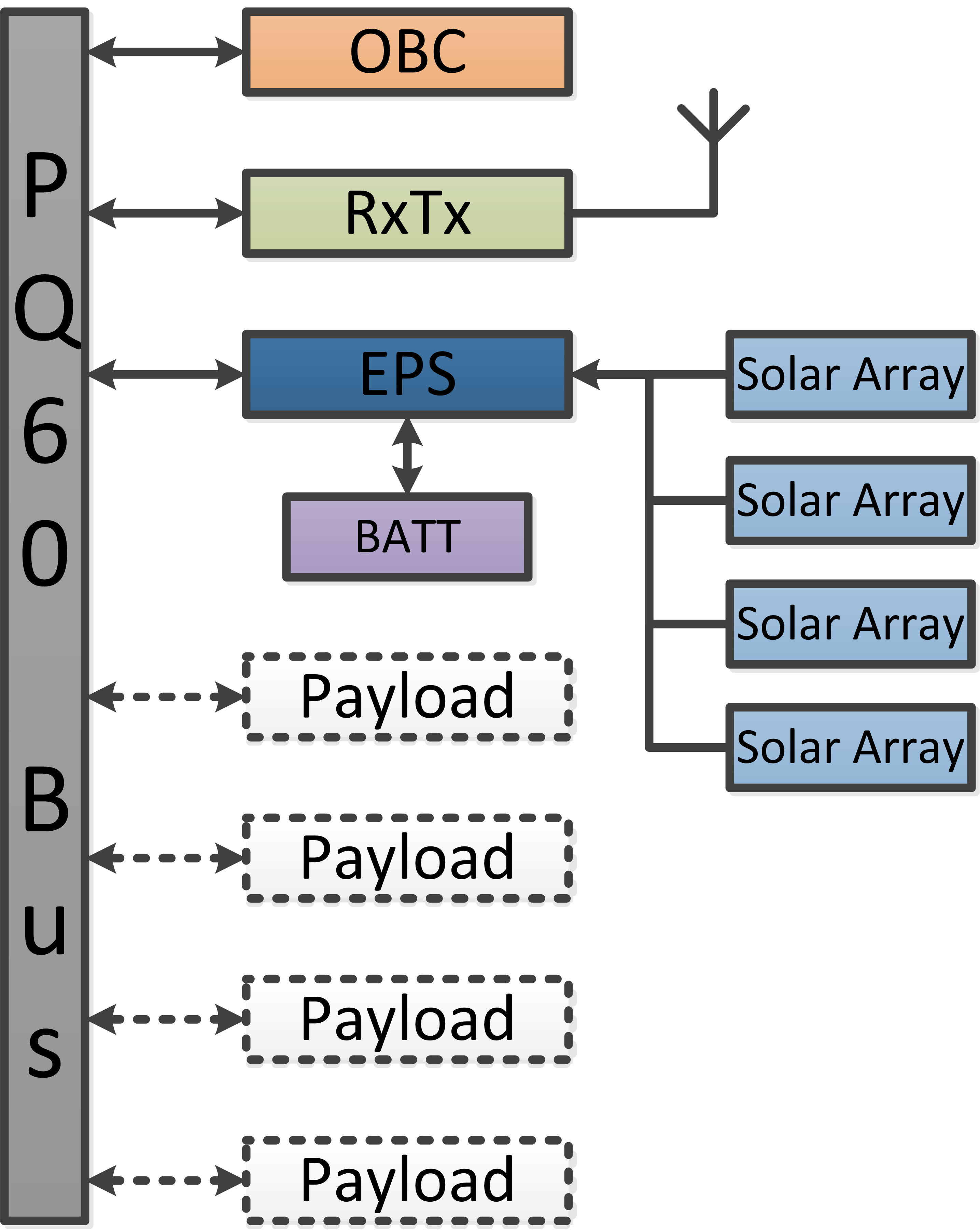
The core of the satellite is the PQ60 Bus, this is a set of interconnections between all the boards in the satellite. It contains power, communications and GPIOs. It is like the spine of the PocketQube satellite. Which would make the OBC or On Board Computer the brain, this is the primary controller for the satellite, it could be as simple as an Arduino or it could be a micro-processor running Linux. While the hardware for the OBC may not be too complex the software needs to be so as to be fault tolerant to keep the satellite running despite any problems it encounters. The RxTx is the radio for communicating with the ground stations, it's great to have a satellite by the data it produces must be communicated to the ground station or it has no purpose. It will be quite high powered to communicate across the vast distances and need to be quite high frequency to both transmit/receive data efficiently but also escape the Earth's ionosphere. The EPS extracts power from the solar cell arrays and charges a battery, it then provides with power to the rest of the satellite via the PQ60 bus.
Optional payload boards depend on the mission scenarios, some missions may call for accurate attitude control of the satellite so will include attitude determining sensors as well as actuators. Other payload boards may include secondary radios, secondary EPSs and cameras. The great thing about the PocketQube standard is that they can be easily slotted into the satellite with minimal electronic hardware changes.
Below is a simplified block diagram of my EPS:
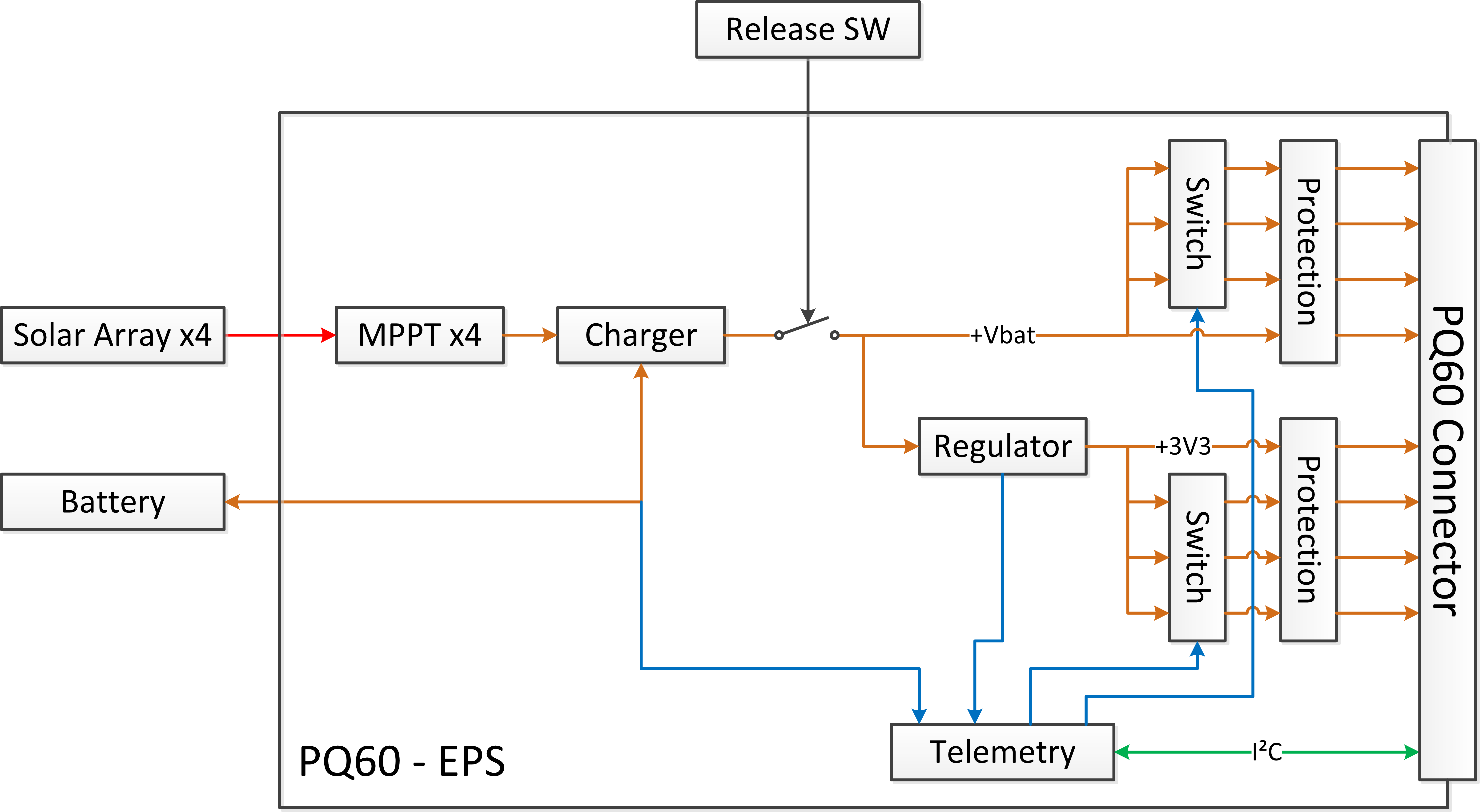
Up to 4 solar cell arrays are connected to the EPS and 4 Maximum Power Point Trackers (MPPTs) seek to extract the most power from the cells in the most efficient way. The aim is to maximise the amount of power absorbed each orbit.
The charger then stores this energy in a battery, typically lithium ion to maximise energy per unit weight. The battery will provide power during periods the satellite is not collecting solar energy or eclipse. This is monitored by the telemetry block so the state of charge can be determined, how much energy is left. The charger also monitors the battery and disconnects it from the rest of the satellite if it becomes dangerously low.
The release switch ensures that the satellite doesn't operate when it is in storage either on the ground or in the launcher.
There are two main power buses on the PQ60 connector, a regulated and protected +3V3 bus with 3 switched outputs and an unregulated but protected battery voltage bus with 3 switched outputs. The protection is to ensure that nothing draws too much power from the battery during fault conditions. This will limit faults to the board that they originate on. The switches allow for high powered loads to be included, for example the QubeCast Max uses an unregulated switched power bus to power the radio allowing it to be shut down independently should it draw too much power.
The telemetry block provides data to the OBC about how much power is flowing to different parts of the satellite and allows some control over this. This is very important during faults to allow for diagnostics from the ground.
I've some further tweaks to my EPS but I hope to be able to show off a more detailed block diagram in future.
Discussions
Become a Hackaday.io Member
Create an account to leave a comment. Already have an account? Log In.