mauswerkz
-
Preparing for PCB tedium
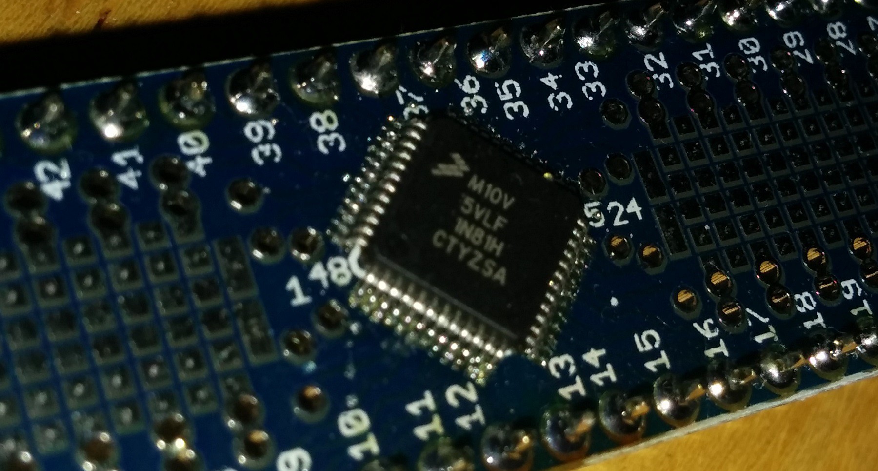
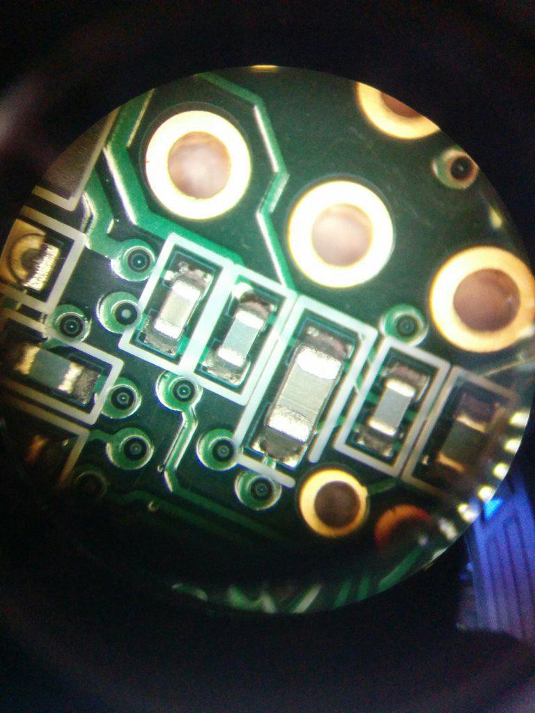
09/27/2015 at 02:53 • 0 commentsThis microscope is new addition to my home electronics workbench. This will help with very small pick-and-place of surface mount components, as well as inspection after reflow and very small reworks. In the spirit of the project (and saving money), I picked it up used from my local HSC electronics surplus store.
The BMS ECU circuit boards are scheduled to arrive Monday. Next weekend with either involve me finishing up assembly of them and beginning programming and testing, or pulling the engine from the BMW. Depends on the availability of shop space at the home of the person who will be helping me with the fabrication/mounting of components in the car.
![]()
![]()
-
BMS ECU PCB (And other fun acronyms)
09/08/2015 at 00:56 • 0 commentsSpent some time over the past week or so developing the BMS ECU. This is the second of three PCBs I'm making for this project. Basically, it handles everything having to do with the battery.
The feature list is:
- 6 CAN busses
- Powertrain CAN (to talk to the inverter and other nodes which will utilize high voltage)
- Pack 1 CAN (for talking to one of the two strings of batteries
- Pack 2 CAN (for talking to the other one)
- Charger 1 CAN (for controlling one charger)
- Charger 2 CAN (for controller the other one)
- Range Extender CAN (Just in case)
- Battery current sensing (for state of charge calculation)
- Contactor control
- Welded contactor detection
- Automatic Precharge
- J1772 (EVSE) Interface for use of public charging stations
- Charge port RGB LED driver
- HV safety interlock loop
- HV isolation monitoring
Individual CAN busses are required for each battery and each charger because each identical item is an identical node and cannot share a bus. Additionally, the chargers and batteries have different speed CAN busses. It makes for a complex product, but it will do the job. Everything will come together and be controlled over the vehicle CAN bus.
![]()
The third board I need to design will be the "gateway" ECU. This will be the bridge between the powertrain CAN bus and the rest of the car (gauges, throttle pedal, key switch, etc). The gateway source code will be open source to allow the system to work with other projects in other platforms. It can be a simple Arduino with a CAN shield and a proto shield, or the ECU I will design.
All three ECUs will be based on the Teensy 3.1. I'm really loving this little device!
- 6 CAN busses
-
Weights and balances
08/01/2015 at 19:57 • 0 commentsNothing new to show about the inverter/transmission at the moment. Still working on tuning the control loops and figuring out how to properly generate torque with an IPM. These are tricky beasts, but I'm getting there. I think once I figure out how to handle field weakening (when it should start and how to implement it effectively), I'll be ready to move to the next step.
I spent a little bit of time today weighing the major components that I have. I bought a load-cell based crane scale for this task.
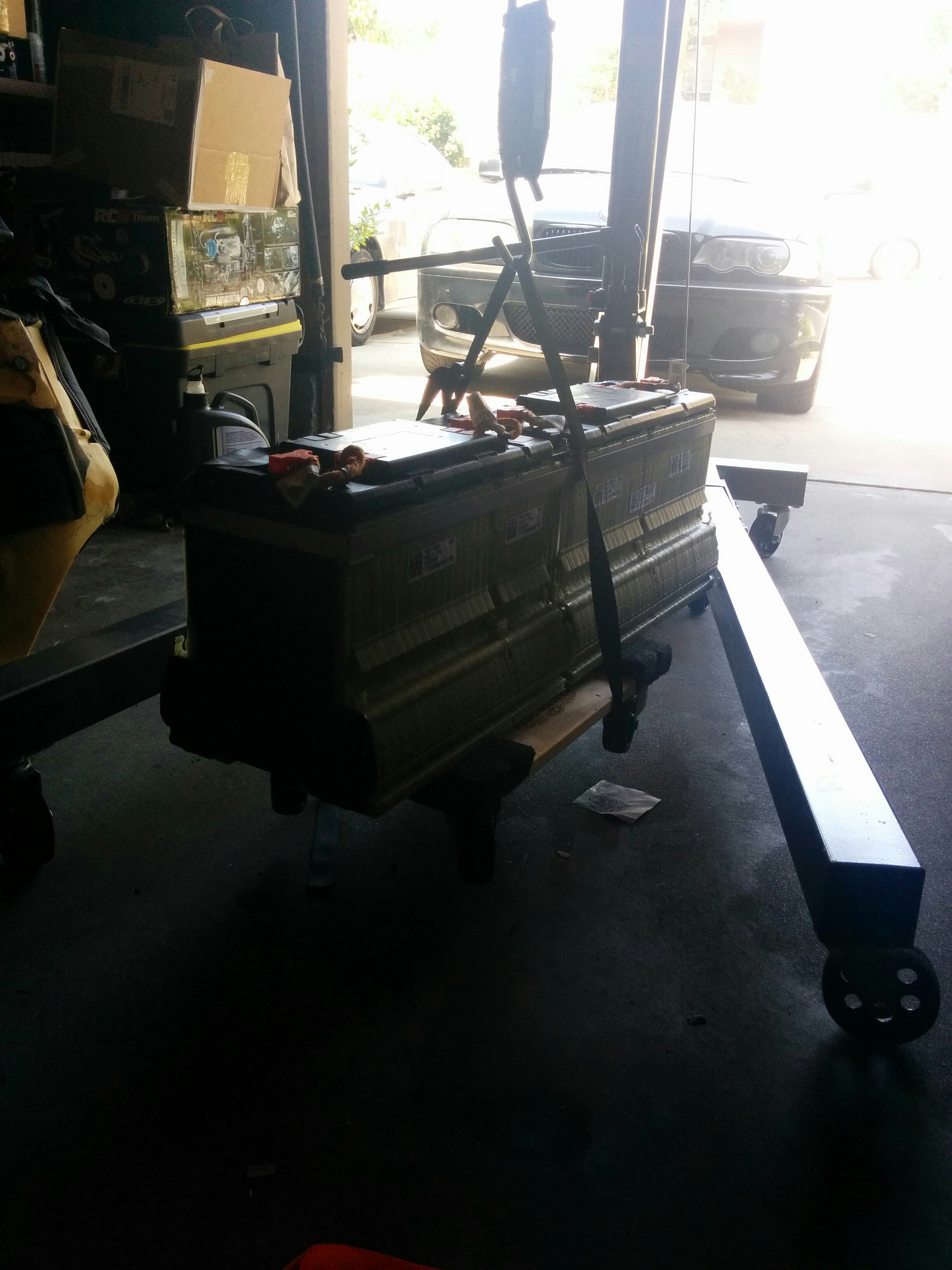
Here's one of my battery modules being weighed, with its future home watching the process.
![]()
The 7kWh module weighs 65.4kg. That's 9.3kg/kWh. So and entire Volt pack worth of cells weighs ~150kg (330lbs) without the enclosure or front BMS/contactor section. So my 29kWh pack should weigh 270kg (595lbs). Better than I was expecting!
This, of course, doesn't include the weight of the battery enclosure/supports I'll have to build.
The Lexus transmission weighs 132kg (290lbs). It's a heavy chunk of metal.
I'll be weighing the major components that come out of the car as I remove them (engine, transmission, exhaust). This, combined with the corner weights I got for the car a few weeks back, will allow me to calculate the battery placements/distribution to ensure that I maintain the same front/rear balance. The Volt packs are somewhat reconfigurable, so I'll be able to fine-tune the weight by moving sub-modules around. The only constraint there is that I'm using the original BMS so need to ensure that that can move with the modules. I don't want to be running high voltage wires through the car other than the two big ones that go to the inverter.
-
Testing the dyno configuration
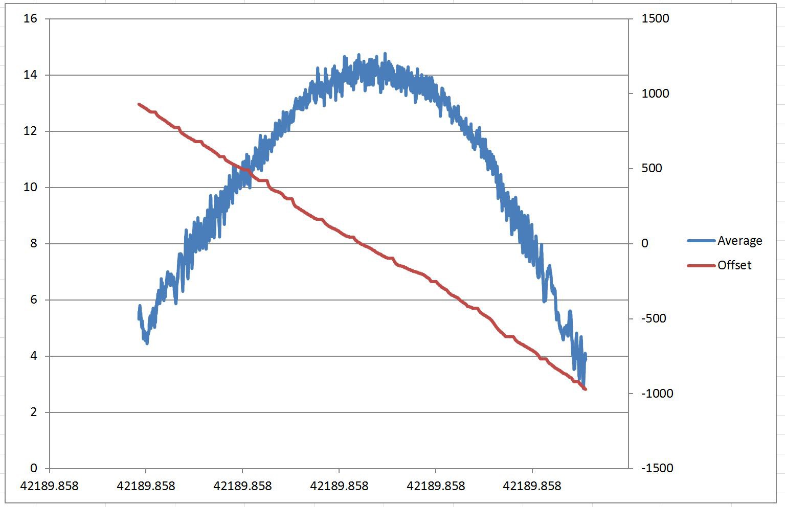
07/10/2015 at 23:09 • 0 commentsI ran one test with an arbitrary load setpoint and the speed set to 1400rpm. This was running on only 200v so I was probably right up against field weakening at this point. Below is a quick plot of the results.
The blue line is the Iq value driven by the speed control loop of the motor acting at the load. As the torque of the driving motor increases, the Iq of the load must increase as well in order to maintain the speed setpoint.![]()
The red line is the offset angle of the opposing (driving) motor.Instead of using Iq and Id decoupled, Id always has a setpoint of zero and Iq is the only current setpoint used. The offset angle is the value (4095 = 360 degrees) which the dq axis is offset from being aligned with the motor angle (a-axis).
For the example plot above, the sweet spot falls at about -50 (only 4 degrees or so). A small number which makes sense for the low speed and low current conditions (<15A).Note that the driving motor was actually set to negative torque (trying to slow the load down). This is why the offset of the driving motor is negative and the Iq current of the load is positive (representing positive torque). This condition simulates regenerative braking.
My experiments will extract the offset angle appropriate for a given Iq and speed. This will go in to a 2D look-up table. So all I have to do to control torque is convert the throttle input to an Iq setpoint, then that pull the associated offset angle from the LUT. This eliminates a whole set of trig operations that would need to be done in the microcontroller if I tried to control the angle by breaking it in to an Id vs Iq relationship.
If the relationship ends up being linear (or very close to it), I could just use a simple scaling and offset equation with no divides. Even better than a LUT, but I'm doubtful it'll be that simple.
This experiment is intended to get the confidence I need that it's all going to work before committing to tearing in to my car and doing the conversion. It should give me enough to make it driveable and give me most of the performance it'll be capable of. I might fine-tune it on a vehicle dyno someday depending on what operating points I can hit with the transmission alone. I'll be limited to the capability of MG1 which is somewhere around half of MG2. So I won't be able to fully characterize MG2 with this method, but hopefully I can extrapolate based on MG1's results. Time will tell. -
Locking the input shaft (Part 2)
07/04/2015 at 05:47 • 0 commentsInput shaft: LOCKED!
![]()
I'm now able to lock the two motors together and drive them against each other as a dyno. Did this briefly today and it worked nicely.
This is an important ability as it lets me tune the offset angle for different speed and torque settings. The IPM motors used in the transmission aren't like simple PMAC or BLDC motors. The IPM motors have a magnetic torque component and a reluctance torque component. This means that I can't just set the current vector to 90 degrees from the rotor magnetic field for maximum torque. I have to set it somewhere in between. I'm not really sure yet whether the optimum angle changes much with speed or torque, but that's what I can find out using this as a dyno.
The tuning process is this:
1. With one of the motors set to zero torque, set the other motor to a certain speed using a speed control loop (torque-producing current as the output).
2. Set a non-zero current setpoint for the first motor.
3. Sweep the offset angle through the expected range and plot the output of the speed control loop.
4. The angle which requires the highest torque from the speed control loop is the optimum angle for that speed and torque operating point.
5. Repeat that for a handful of strategically selected operating points and plot the relationships.
I'll start with a constant offset value for the unknown motor while tuning the other one. Once I've done that for both motors, I just have to put them in to a look-up table that is used while driving so I always have the optimum offset angle for every pedal position.
I'm really looking forward to getting this tuning done so that I can then write the code that implements "throttle" control of the motor torque. This will be fun because it's where I'll set up the framework for tuning the pedal feel. It will also be when I program the gear change required for MG2. That will be an interesting challenge.
-
Locking the input shaft (Part 1)
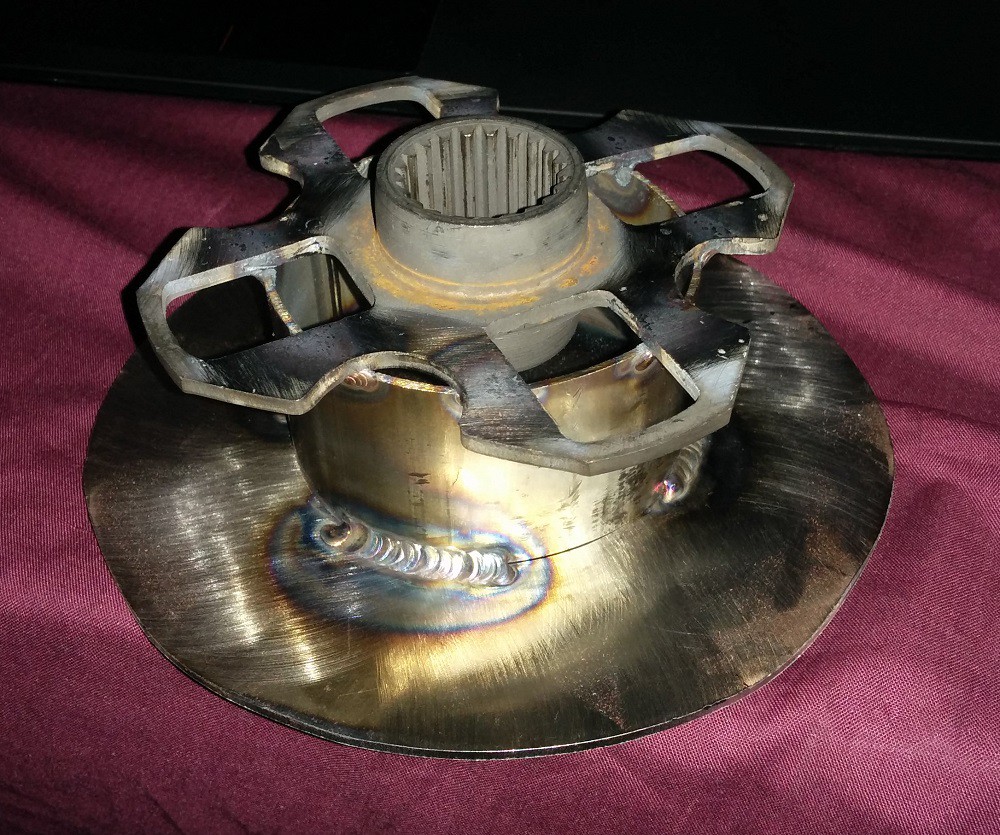
07/03/2015 at 03:27 • 0 commentsHad a friend help me fabricate the piece that I'll use to lock the input shaft of the transmission.
![]() The splines are from the center piece of a clutch for an old Toyota Celica. It's a 21-tooth 28mm diameter spline. A google search of the spline dimensions brought up the clutch alignment tool for a 70's Celica. You could probably go backward from the clutch alignment tool to find other cars with the same spline. Apparently Toyota used the same size splines on several other vehicles including the Rav4. I find itquite amusing that the clutch from an old Toyota fits perfectly on the input shaft of a 2007 Lexus Hybrid.
The splines are from the center piece of a clutch for an old Toyota Celica. It's a 21-tooth 28mm diameter spline. A google search of the spline dimensions brought up the clutch alignment tool for a 70's Celica. You could probably go backward from the clutch alignment tool to find other cars with the same spline. Apparently Toyota used the same size splines on several other vehicles including the Rav4. I find itquite amusing that the clutch from an old Toyota fits perfectly on the input shaft of a 2007 Lexus Hybrid.The clutch hub was welded to a piece of 3" exhaust pipe which was then welded to a circular plate. I'll drill holes in the plate this weekend and bolt it to a sheet of 6mm aluminum which will also bolt to the bellhousing to lock the shaft from spinning.
All up, it cost me about $30 plus dinner for my friend for the welding and some scrap steel he had laying around.
-
New Control Board: It Works!
06/28/2015 at 05:21 • 0 commentsFirst spins on the new control board happened today. Getting the code tuned in. The motors are making some very fun sounds!
The slow ramp-rate of the motor here is due to the current limited of the charger I'm using as a power supply. I've got it set to 1A @200v for safety. I certainly have to be careful with regen here. I managed to get the bus up over 700v a few times while actively spinning it down to a stop. That'll be fine when there are batteries powering it, but not so good with the charger that's only rated to 430v.
Here's a quick teaser video of it spinning on up one of the motors. Have to hook up the electric oil pump to keep things lubricated and close the clutches, then I can spin MG2 up and have it play along (or against) MG1.
After that, it's just a matter of software tweaking and tuning. Will have to generate a look-up table for each motor at various operating points. Handy that the transmission will work as a dyno by driving the motors against each other.
I've ordered a radiator and some hose so I can get cooling set up, then I'm good to go. That should be ready by next weekend. Good thing too, since it's a long one. -
Board Populated!
06/14/2015 at 00:42 • 0 comments![]()
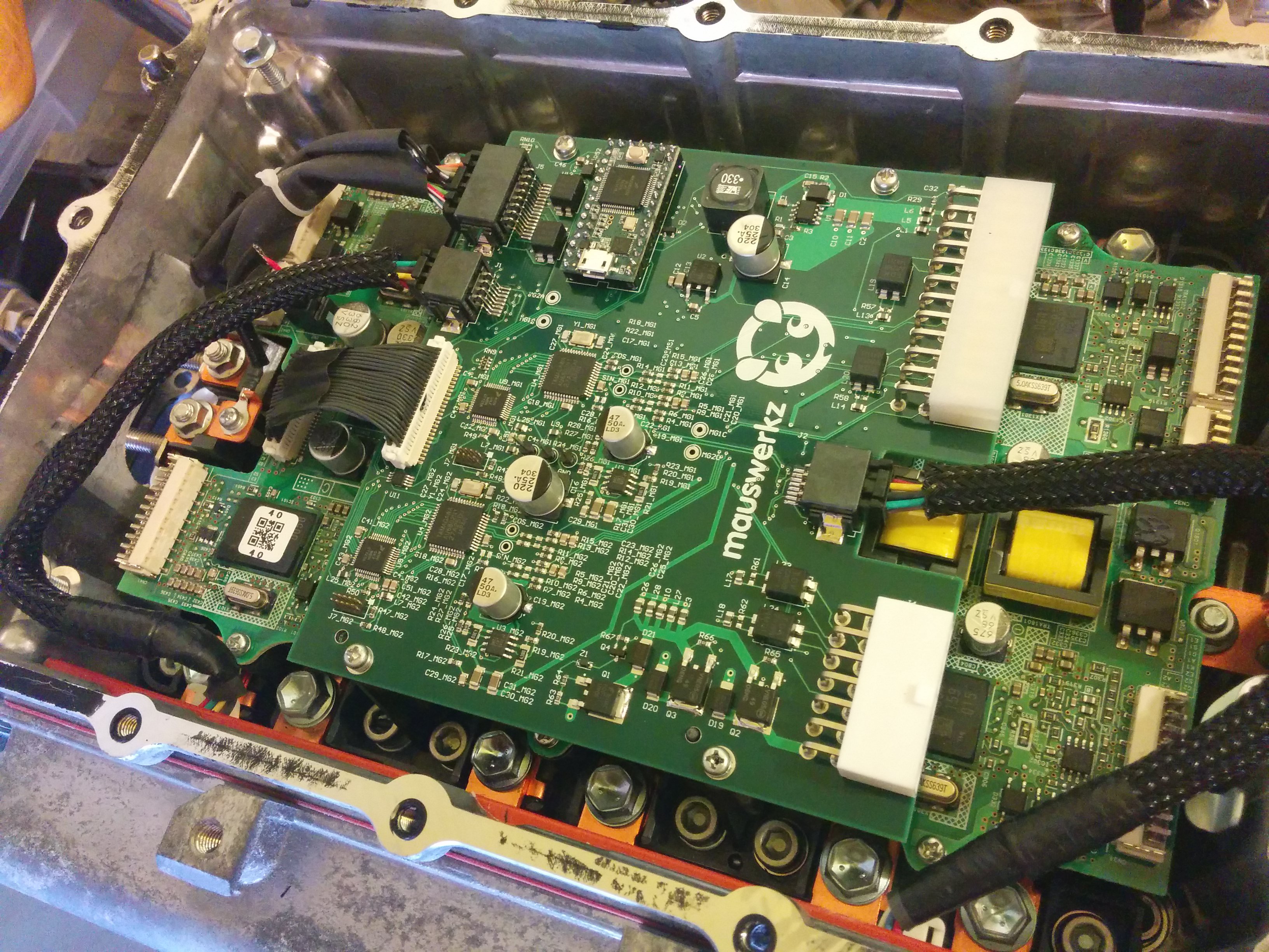
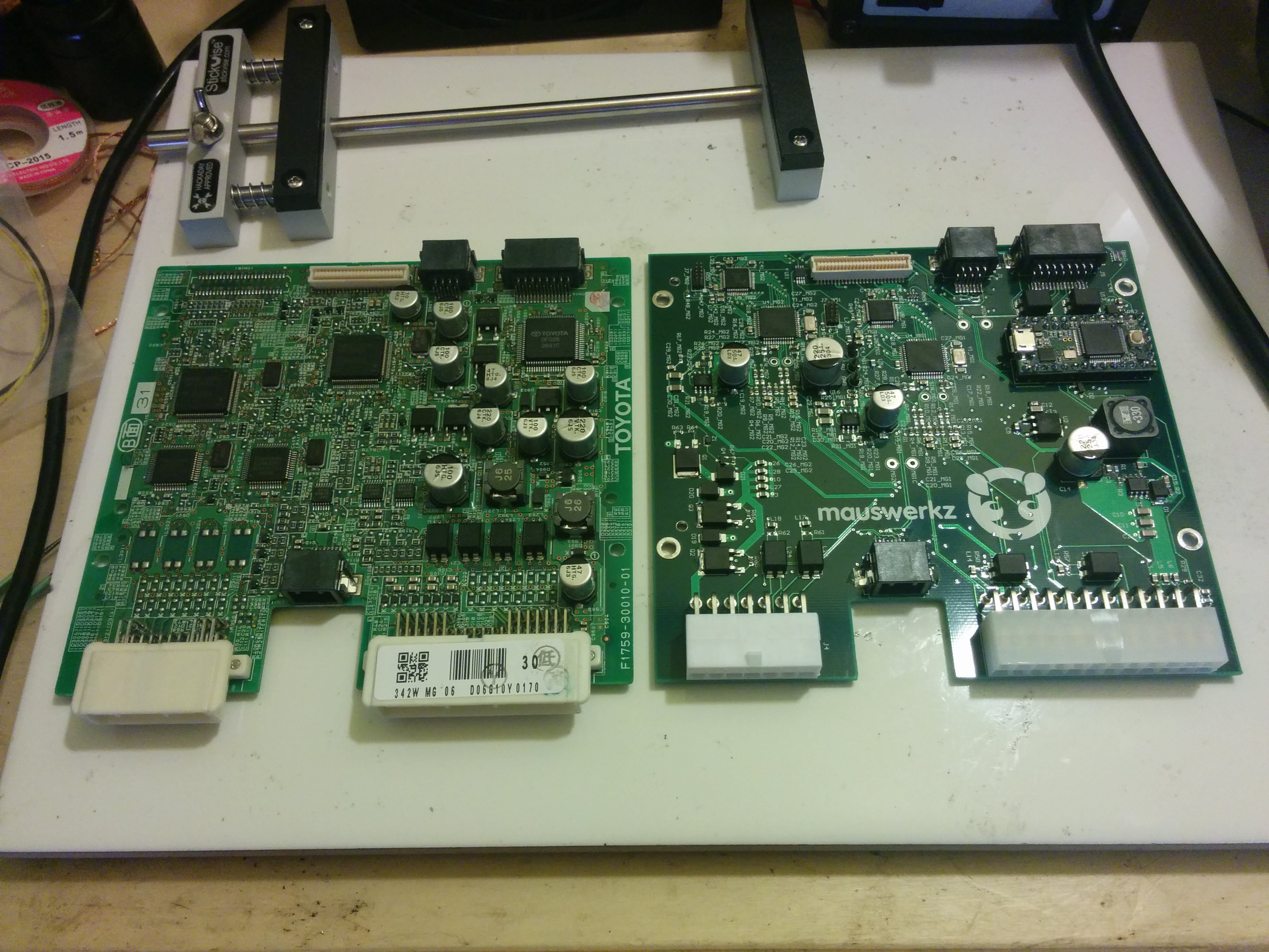
Finished populating the new board today. It's sitting on my bench right now with a blinking LED, so that's a good sign! Still got a lot of testing and verification to do, but it's looking good so far. I need to do some programming to really test out the board, so that's where I'm at now.
Pictured below is the new board next to the original Toyota/Lexus board
Picture above is the new board installed in the inverter. Everything plugs in just like it's supposed to!
![]()
-
Component choices and learning a new toolchain
06/12/2015 at 03:57 • 0 comments
I got started with microcontrollers, like many, with Arduino. This set me on the path to use Atmel parts in my personal projects. First I started embedding Arduino-compatible AVR devices in projects, using the Arduino IDE to code for them, and an AVR-ISP clone to program them. Once I started doing more complex projects, I looked at other Atmel devices beyond those supported by the Arduino IDE. I moved to Atmel Studio and played with the xmega series of devices. Still 8-bit, but with more "grown up" peripherals and a higher clock speed. It was an xmega device that ran my first 3-phase inverter.![]()
With this new project I wanted to take another step up. I looked at Atmel's ARM offerings but couldn't find the right combination of peripherals, performance, and motor-control libraries so I decided to branch out. In my searches, I came across the Freescale V-series ARM devices. These are aimed towards motor control and power conversion, have the right collection of peripherals, and a motor control library is offered for use on them which will greatly simplify the coding portion of the project. These seem to be a good fit.
My inverter control board has three microcontrollers and two resolver-to-digital (R2D) converters. There is one microcontroller and R2D pair per motor and a main "supervisory" microcontroller.
My specific choices of device are:
2x Freescale MKV10Z32VLF7 32-bit ARM Cortex M0+ @72MHz (Freescale product page)
1x Teensy 3.1 (Freescale MK20DX256VLH7) 32-bit ARM Cortex M4 @ 72MHz (Teensy product page)
The MKV10's will do the PWM generation, read the R2D's and phase currents, and perform the vector control calculations for the motors. The current controller setpoints will be fed to these via SPI from the Teensy. The speed control loops, transmission control, CAN link, and supervisory functions will be performed in the Teensy. It'll have more on its plate, but the calculations it needs to do aren't as numerically intense, so it should be a good balance.
I'm getting used to the Freescale toolchain (Kinetis Design Studio). It's a different environment than I'm familiar with (Eclipse for KDS vs Visual Studio for AS), but there are some very handy tools included. I'm using a Freedom KL25Z dev board as my programmer until I can pick up a proper one.
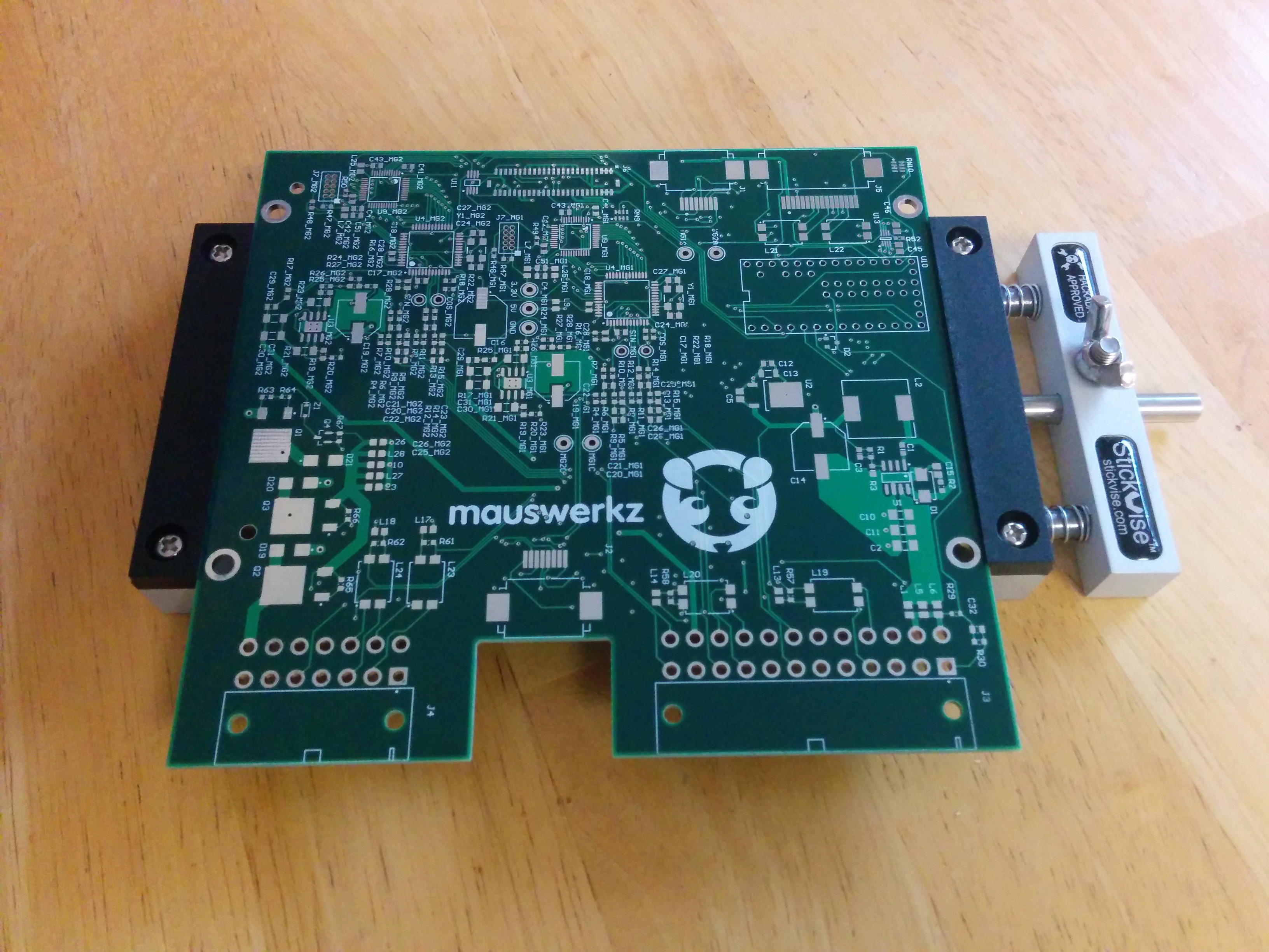
Meanwhile, I've made some progress assembling my board. Ordered a few of the wrong parts, which has delayed me a bit, but I got the power supply components installed and working. I've populated the bottom side of the board (the stick vise sure came in handy for that!) and will do the top side this weekend. If only I could get some 22k ohm SMD resistor arrays locally! Hardly worth placing a digikey order just for those.
Anyway, keep an eye out for more updates over the next few days.
-
PCB Arrived, and a fancy new tool
06/11/2015 at 02:08 • 0 commentsTwo things arrived today: the PCB, and the Stickvise I won in the HaD giveaway. Here they are together.
![]()
Looks like it's going to be handy! Hopefully the plastic holders can withstand the heat of hot-air soldering going on in their vicinity. I don't have a 3D printer to replace them, but if I need to, I'll probably cut some from HDPE as an upgrade.
I also have all the components to go on the board. I'll start with the power supply (lower right) and make sure that's happy before putting the rest of my parts on. If all goes well, I get to spend the next several weeks getting the firmware to the point where I can spin the motors. For tuning, I'll use the motors against each other as a dyno built in to the transmission. This is really the only way to properly tune IPM parameters. Thankfully, the dyno is free!
DIY Electric Vehicle from Recycled Parts
Converting a car to electric drive using recycled and salvaged EV and hybrid components.


 The splines are from the center piece of a clutch for an old Toyota Celica. It's a 21-tooth 28mm diameter spline. A google search of the spline dimensions brought up the clutch alignment tool for a 70's Celica. You could probably go backward from the clutch alignment tool to find other cars with the same spline. Apparently Toyota used the same size splines on several other vehicles including the Rav4. I find itquite amusing that the clutch from an old Toyota fits perfectly on the input shaft of a 2007 Lexus Hybrid.