 mauswerkz
-
Rear batteries mounted!
04/26/2016 at 04:27 • 0 commentsWell, kinda. The rear LOWER batteries are mounted and bolted in place. The upper battery has been test-fit and seems to fit nicely.
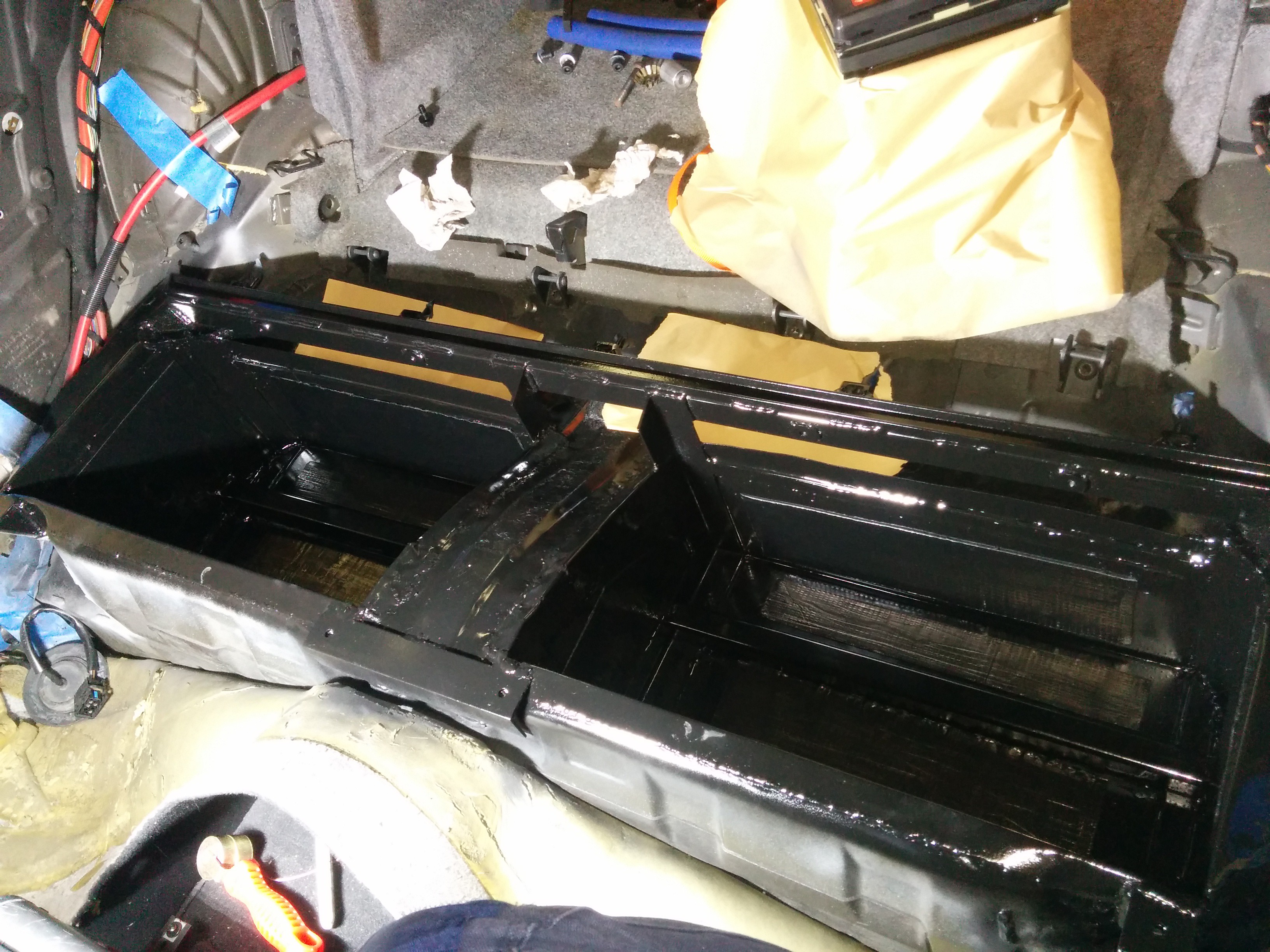
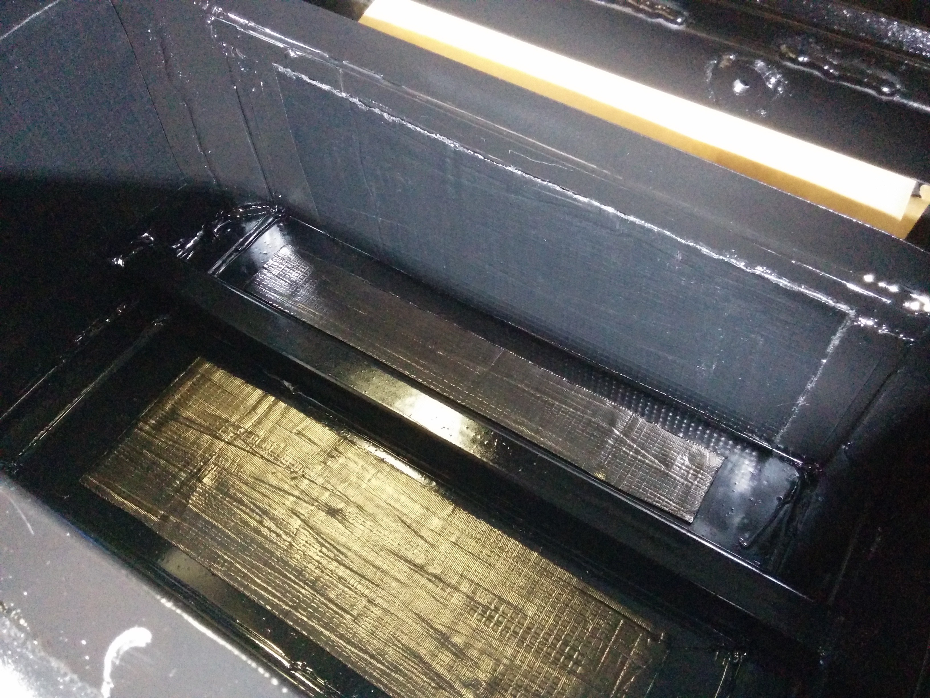
The lower battery boxes have been sealed and painted. I applied some sound deadening material to the broad panels to keep them from vibrating. The before and after "knock" test of the sound is quite profound. I think it will work nicely.
![]()
![]()
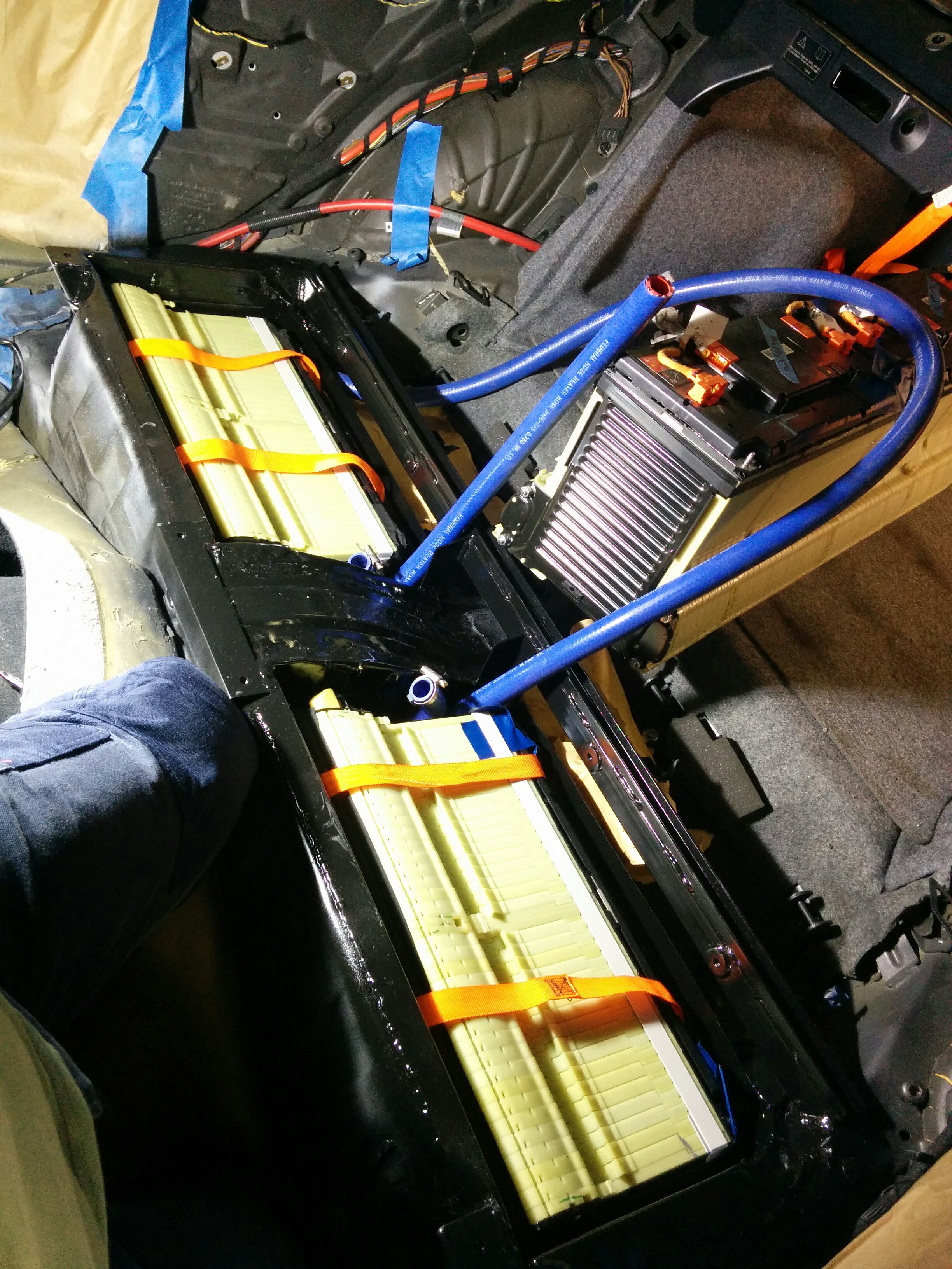
Once that was done, the lower batteries were lowered in place (with hoses attached) and bolted in. Very tidy! (pictured here without the clamping braces)
![]()
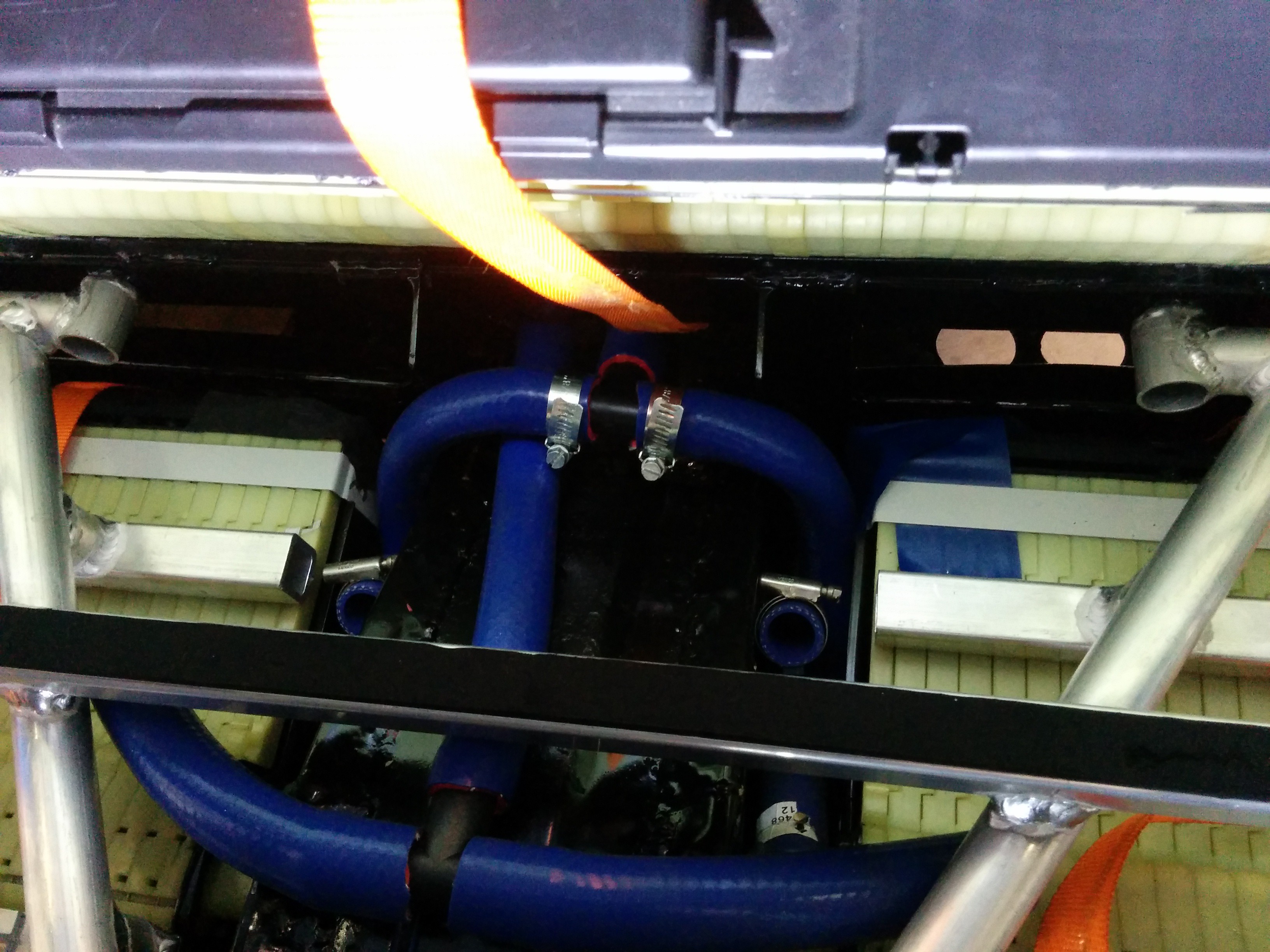
I started routing the coolant lines for the lower batteries. Will need to buy/make some couplers to join the two upper hoses to the tee piece. The lower hoses are already connected (the ones with the hose clamps).
![]()
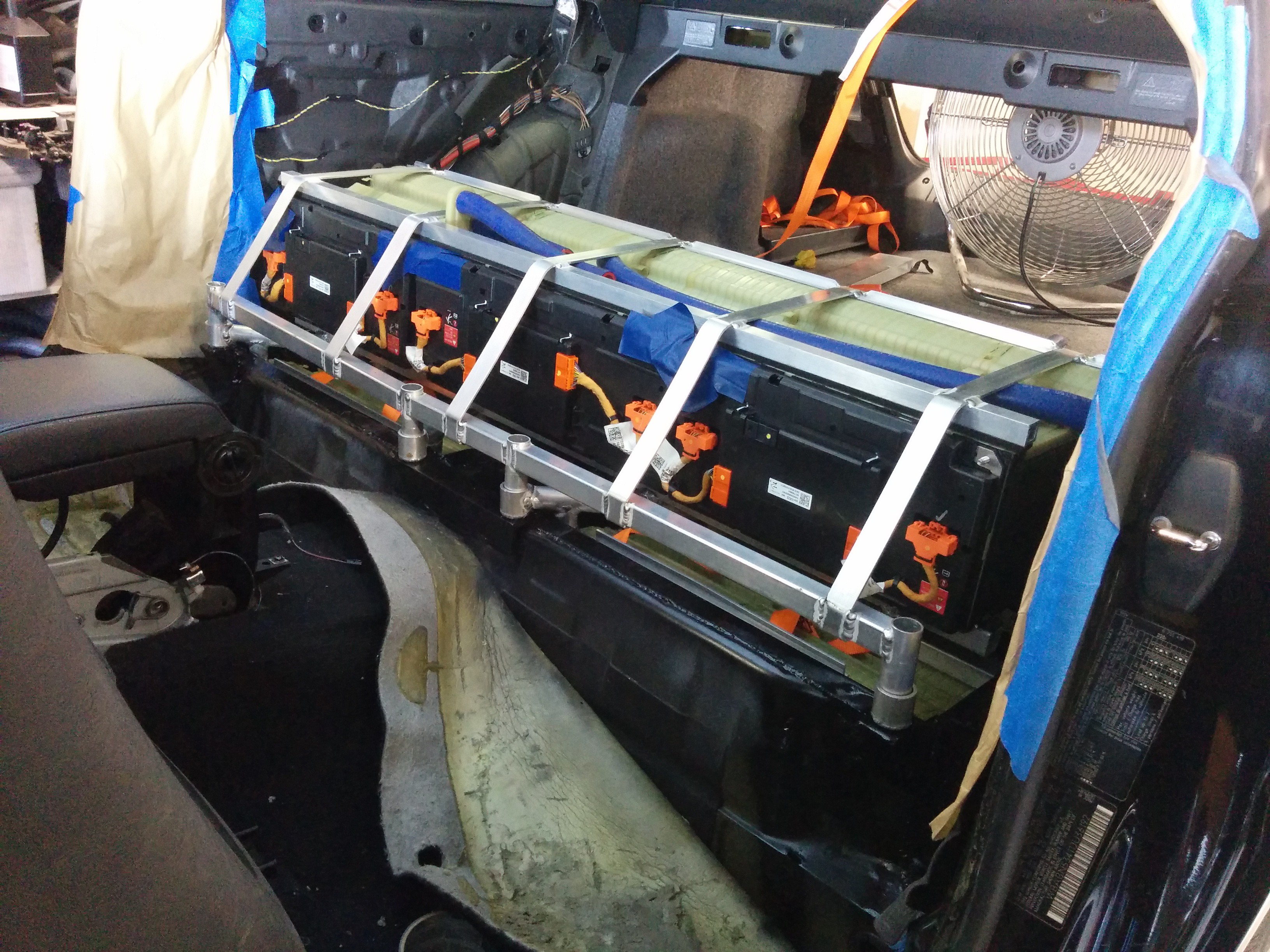
Below is a test fit of the upper battery and its securing structure. It's not bolted down in this photo, but is shows what the final configuration will be. The coolant ports are at the top in this configuration. Long hoses will loop around to meet the tee pieces that will attach to the hoses coming in through the grommets just behind the battery.
![]()
The BMS wiring is dead easy! I just have to hack up the original low voltage harness and extend it to reach the main BMS ECU (see previous update) which will be inside the front battery box. I've already stripped most of the tape and loom from the harness where required. The hardest part will be running the extended harness wiring up under the hood.
-
Testing supporting components
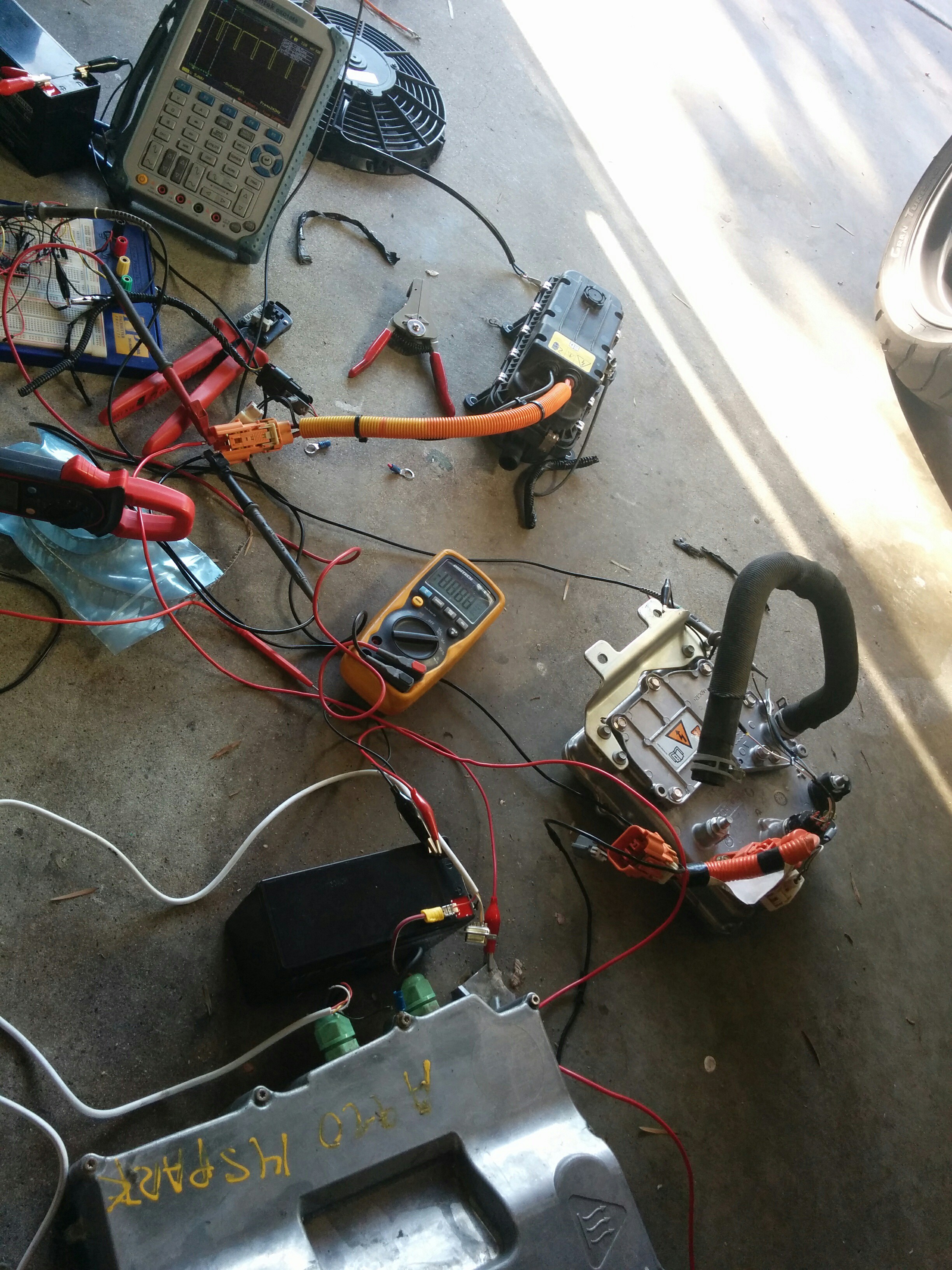
05/01/2016 at 03:49 • 0 commentsI spent some time today figuring out how to use a couple of the supporting components for my build. These include the power steering pump, DC-DC converter, and coolant heater.
![]()
I used a Chevy Spark charger (same as the Volt's) as a high voltage power supply and powered up the components. The DC-DC is from a Ford Focus EV. It powers up its output immediately upon application of high voltage. This is extremely convenient for me, though I imagine it could cause trouble with precharge in other conversions. This isn't a concern for me though. The low voltage wiring is 3 wires. Two wires are a differential data pair and the third seems to be floating. I thought it might be a disable line but it doesn't seem to respond to having 12V put on it, though I was using a 10k resistor and it appeared to clamp to a bit over 5V. I wasn't game to try a lower value resistor, so I just left it be, happy that it works anyway.
The coolant heater is also from the Focus EV. Super simple PWM input to drive that. The charger wasn't up to the task of driving it (which is good, since I clearly didn't have any coolant in it!). It did seem to react to the input signal I fed it, so I'll play with it more once it's in the car. This is used for the cabin heater and battery heating, when required during charging.
The power steering pump is from an Astra. I had to buy another one since the one I installed in the car wouldn't power up. I tested this one on its own and it spins up happily, so I'll swap them tomorrow.
-
Front battery securing and rear battery wiring
05/03/2016 at 02:34 • 0 commentsThis weekend the securing fixture for the front battery was fabricated. It's a fairly simple arrangement, holding the batteries side by side in contact with each other. A "C" channel on either side holds the outboard edges of the batteries and a strap down the middle holds the inboard edges. The whole thing bolts down to the cross-beams I installed. All bolted down, it seems quite secure. The entire assembly is removable, which will allow a tray to be fabricated out of aluminum sheet metal for the batteries to sit in. A cover will be installed over the top (probably made from fiberglass and/or carbon fiber) to seal the front battery box. The BMS, contactors, and current sensor will all live in the space between the front batteries.
![]()
![]()
The power steering pump had to be replaced. For some reason, the first one I bought was dead. This one works fine. we powered it up and loaded it for the first time with no issues. Turned the wheel against the lock and the pump draws more current just as expected.I also finished up the coolant routing for the lower battery (just waiting on some clamps to arrive) and installed the first high voltage connection. The flat orange connection cable-tied to the bar is made from one of the original bus bars from the Volt battery. It was folded to the right shape, cut, and stripped. A quick bead formed on the cut corners with the TIG keeps the laminations from separating. The stack is then drilled to size. Very handy stuff, Much neater than heavy gauge cable I think.
![]()
-
Finishing up underneath, enclosing front battery
06/05/2016 at 23:45 • 0 commentsAnd there goes another month! We got sidetracked by some reinforcement that was needed to the rear battery tie-down. That's sorted out now. Also lost a weekend to a out-of-town trip.
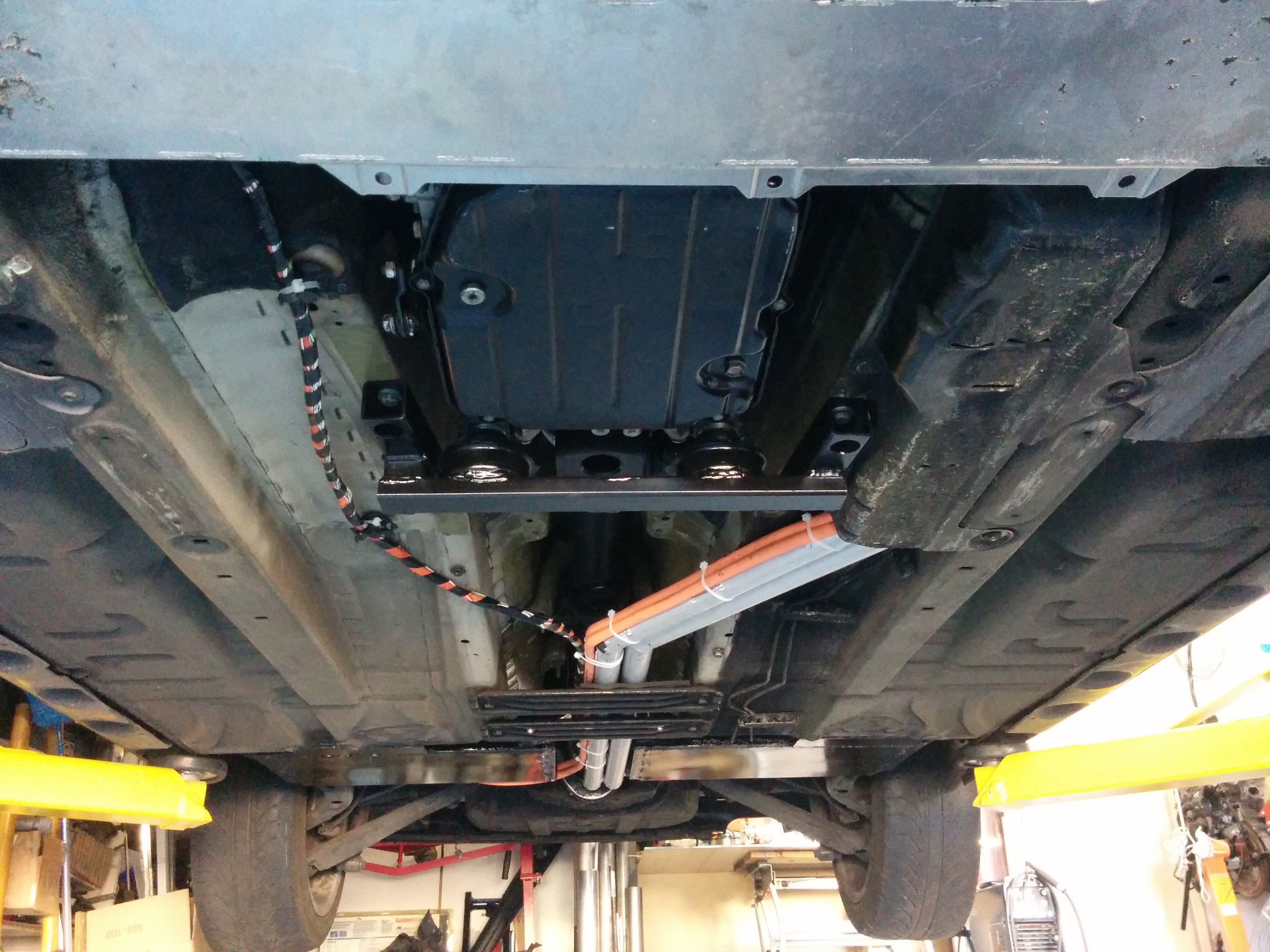
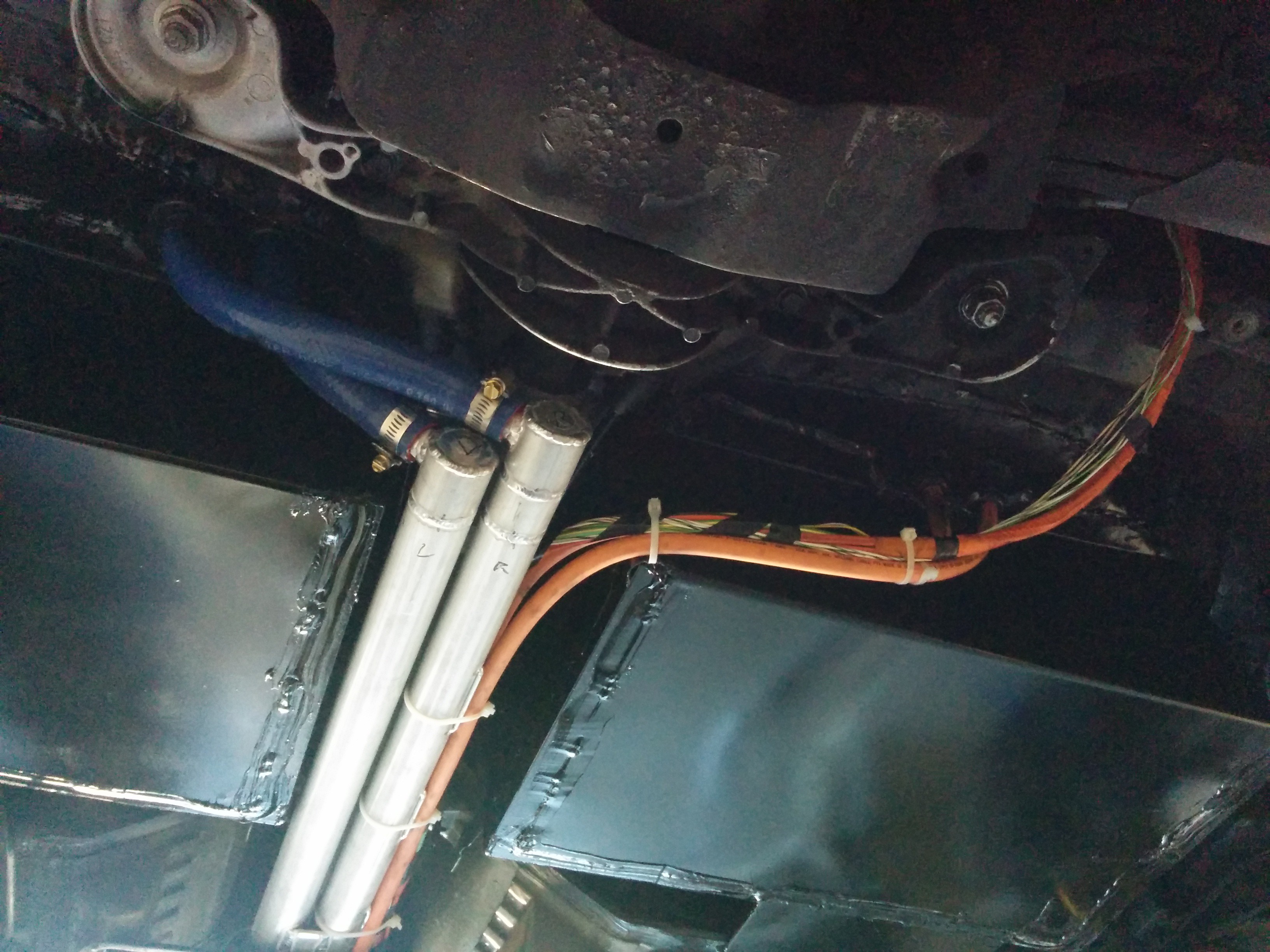
The charge port cabling and HV cables between the front and rear battery pack are done and in place. The coolant tubes are also installed and used as support for some of the cabling.
![]()
![]()
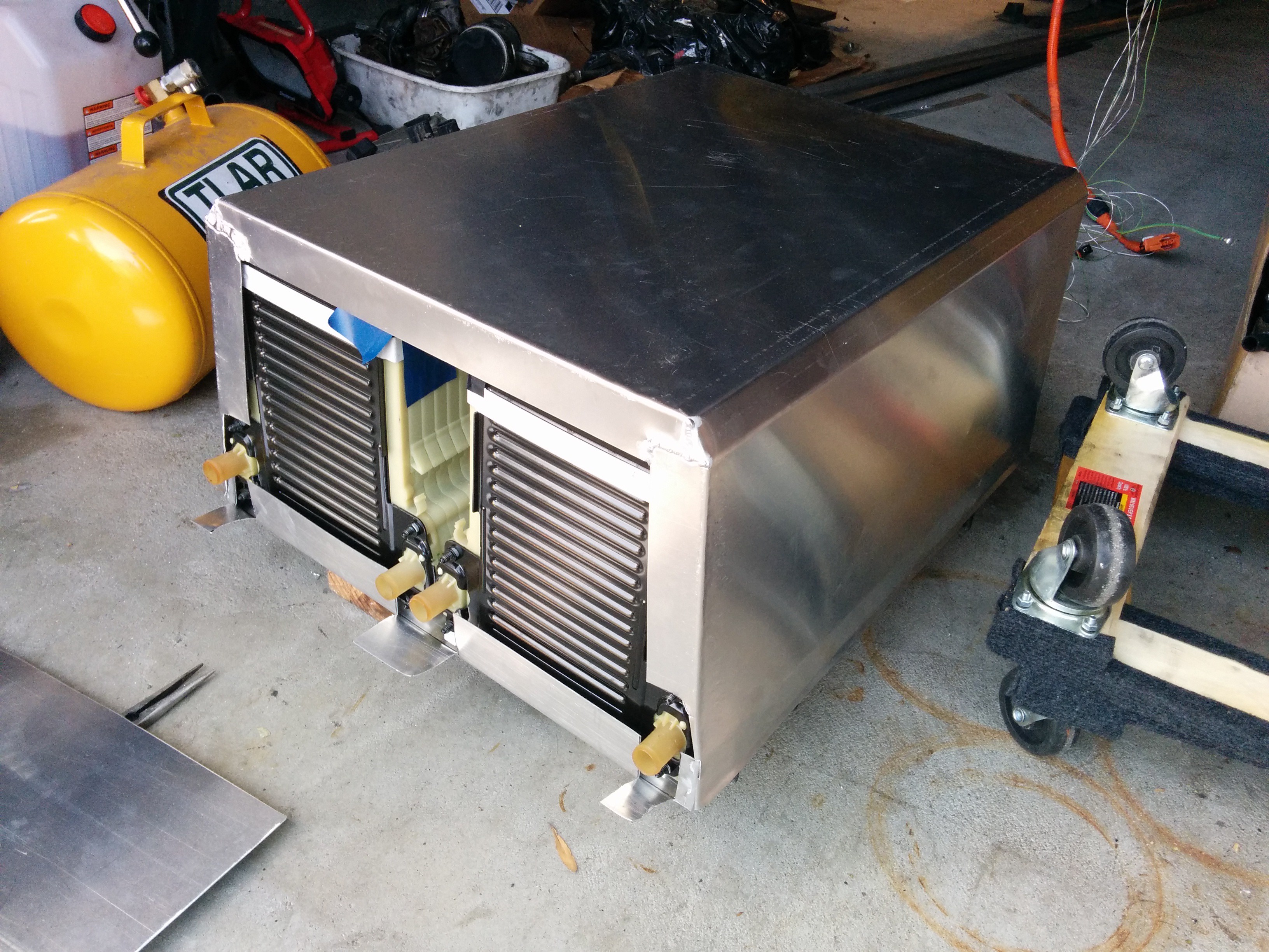
Moving to the front of the car, we've started enclosing the front of the battery box. The bottom of the box is a tray which the structural portion is installed in to. The batteries go in on top of the tray and mount to the beams in the front of the car, then a box formed from sheet metal is placed over the top. The top will be held on by a rack which will span the frame rails and support the inverter, chargers, DC-DC converter, and heater.
![]()
The front of the box isn't installed yet in this photo. The coolant ports will not be covered by the lid, instead a panel will be installed which will seal against the front of the box and allow the hoses to protrude through.
The contactors, current sensor, and BMS ECU will be installed in the space between the batteries. I've already started this, though I didn't take any photos.
Still to do:
Wire the LV BMS circuits
Wire the HV BMS circuits
Install inverter, chargers, DC-DC, heater
Finish cooling plumbing and wire pumps/temperature sensing
Leak-check the cooling system then fill and test
Install brake vacuum pump, reservoir, and tubing.
Precharge relay and resistors
HV wiring to chargers, DC-DC, inverter, heater
LV wiring to chargers, DC-DC, inverter, heater
Build Arduino-based "gateway" ECU and connect to things like the accelerator pedal, gear selector, and gauge cluster (not as big a job as it might sound).
FIRMWARE!!!! (a bigger job than it might sound).
Finish up charge port LEDs and door sensing.
Wire up the power steering pump to 12V and ignition
Start putting interior back together
Make a cover for the rear battery (carbon fiber?)
Fabricate and install undertray (optional)
I'm sure there are a ton of other little things I'm forgetting.
We have to get all the heavy-duty mechanical stuff (cutting, welding, fabrication) done by the end of June as the guy that's helping me with it wants his lift and garage back. The car will then come home to me where it will be finished off with electrical stuff and firmware stuff that doesn't get done on the lift.
-
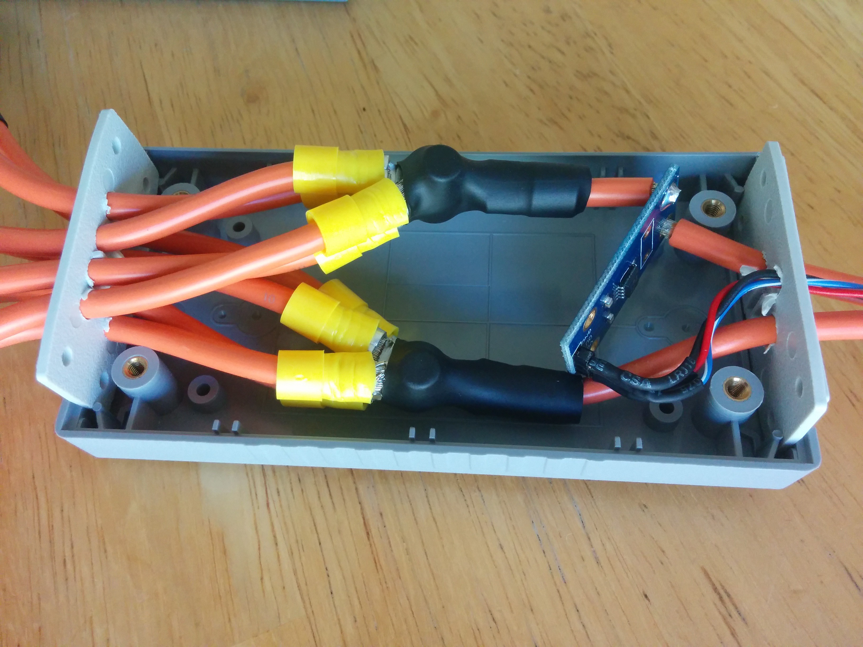
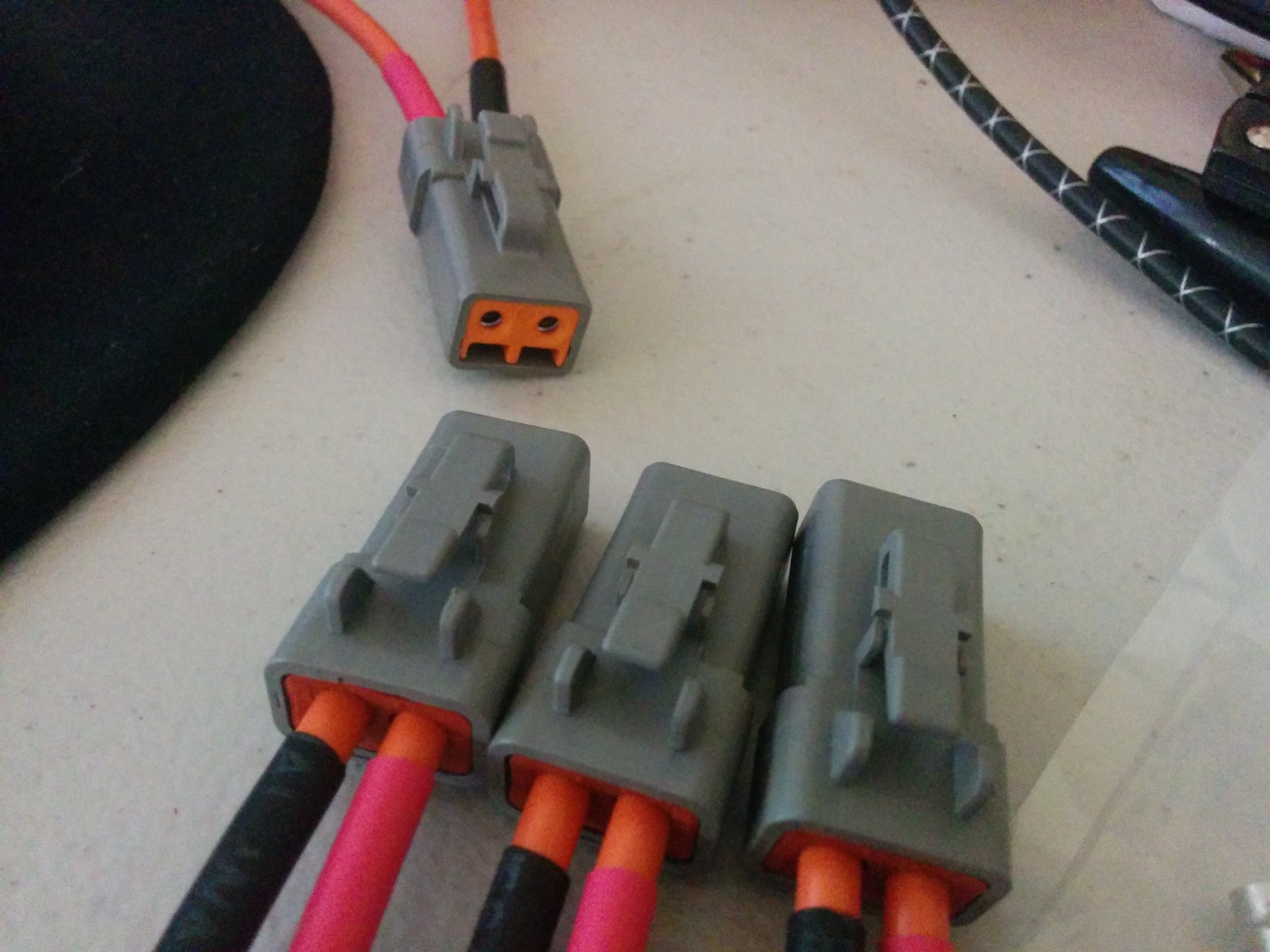
Mid-voltage distribution box
06/11/2016 at 20:52 • 0 commentsA few quick photos of the mid-voltage (~350V) distribution box. This will distribute power between the battery, chargers, DC-DC converter, and heater. There's a current sensor in there as well. Once I've tested it, I'll fill the enclosure with silicone to make sure it's sealed up as it will live under the hood.![]()
![]()
![]()
I just love how much some nice connectors and heat shrink tubing can add a touch a professionalism to a project.
-
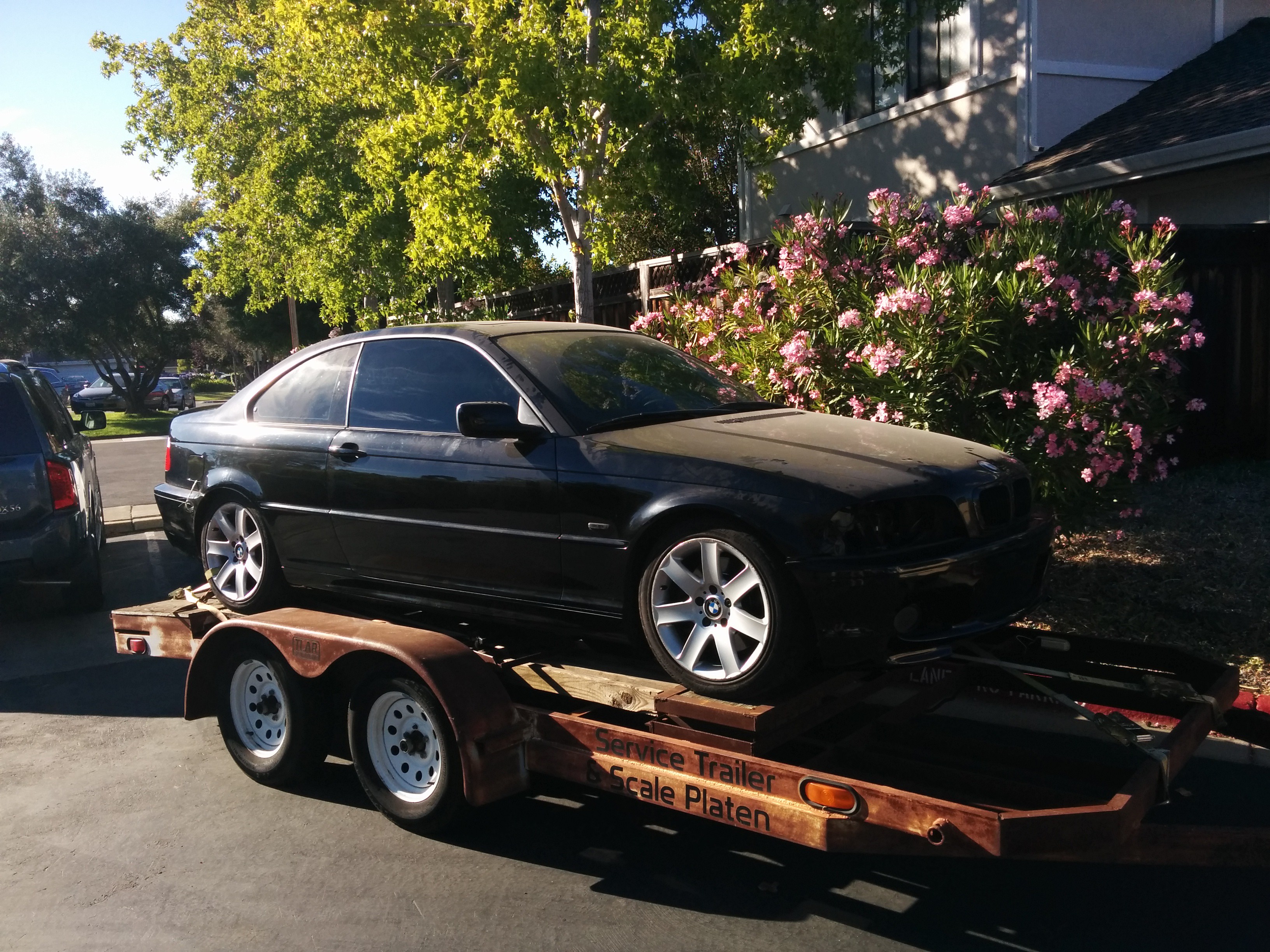
Wrapping up the mechanical fabrication
06/30/2016 at 04:16 • 0 commentsThe mechanical fabrication is very close to being complete! So close in fact that the car came home with me this weekend (though on a trailer, not under it's own power). All that's left for the mechanical work is to finish the frame that straddles the front battery and to which the inverter, charger, DC-DC converter, and coolant heater mount to. And a return manifold for the coolant loops.
Look how dirty it is! The only clean spots are the door windows (since they were rolled down since October) and the trunk lid (since it was open that whole time). The car was in a garage the whole time. This is all dust that collected on it in there.
![]()
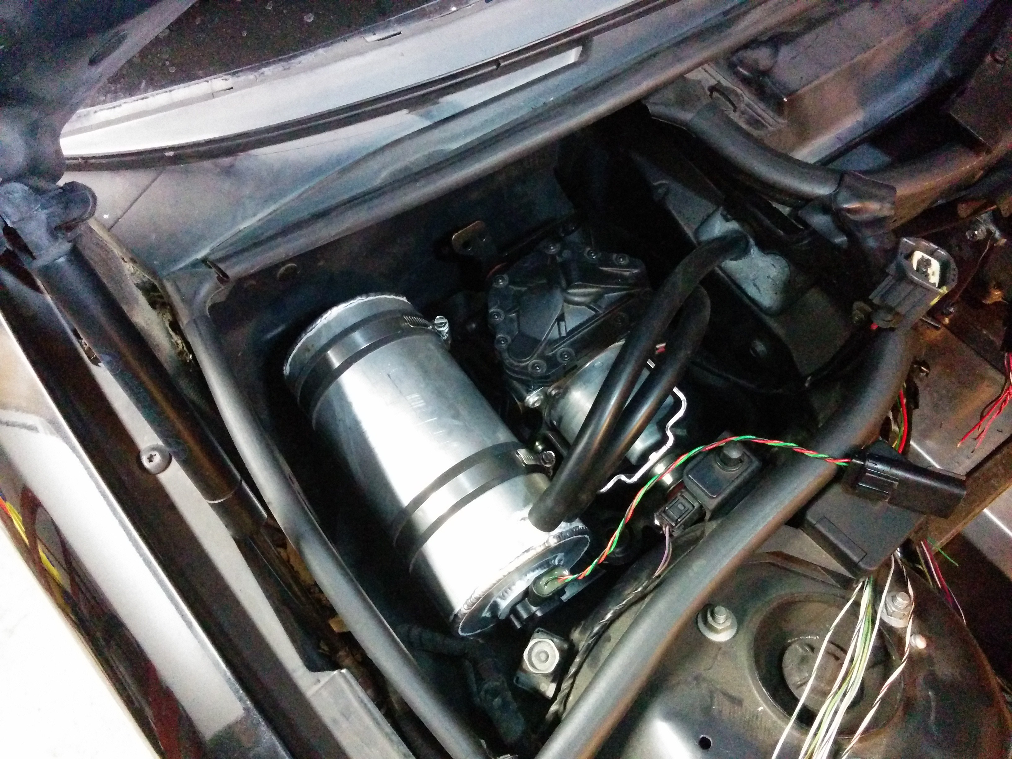
The brake vaccuum pump (from a Ford F150) is mounted in the empty cubby behind the front passenger side strut tower. The tank is an aluminum pipe with its ends capped. There's a GM manifold pressure sensor to monitor the vacuum level and help control the pump (same method I used on my previous EV conversion).
![]()
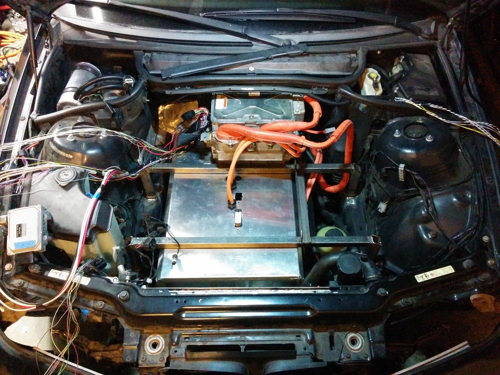
The front battery box cover is in place. I have to finish the wiring inside it and terminate it all in to the connectors on top. There are 4 glands for HV cables as well. Two coming from the rear battery, and two heading to the inverter. The charger will mount to the left in this photo, DC-DC and coolant heater will mount on the right (above the steering pump). The inverter is mounted to the frame already, so that's where it will live. The small box in the far left of the frame is the transmission oil pump controller. I need to shorten the wiring going to that and mount it somewhere with good airflow.
![]()
-
Wrapping up the BMS Hardware
07/04/2016 at 04:37 • 0 commentsGot the BMS hardware mostly sorted out over the past couple days. All the wiring to the batteries and contactors is complete. Still have to sort out the wiring for the charge port (LEDs, Proximity, and Pilot).
With the BMS CAN wiring complete I was finally able to get the BMS talking to the entire pack at once. Here's a quick screen capture of some of the distilled data from the Volt battery OEM BMS modules.![]()
For packs from two different cars and sitting for 8 months (I balanced them back in September), the voltage difference between the highest and lowest cell is very tight. I'm quite pleased!
I made a quick video showing the BMS controlling the contactors, including precharge and welded contactor detection.
Not much to see other than the voltage coming up. Most of the interesting stuff can be heard.
During the closing sequence, there are 5 clicks. They are (in order):
Battery negative contactor closing
Battery pack split contactor closing
Precharge relay closing
Battery positive contactor closing
Precharge relay opening.During discharge, you can hear 3 clicks:
Battery positive contactor opening
(Delay while it waits for voltage to drop, showing it actually opened and isn't welded)
Battery negative contactor opening
Battery pack split contactor openingThe pack split contactor separates the rear battery pack from the front to keep voltages in the battery box at a lower level while sitting idle. When closed, it places both packs in series.
Once that was sorted out, I put the battery cover on and am ready to finish wiring in the inverter. That should take a handful of hours, after which I may be ready to do the first spin of the motors in the car and on the actual battery pack!
![]()
It's starting to feel like it's getting close now!
-
The Wheels Spin!
07/07/2016 at 04:43 • 0 commentsNot going to say much here except that this is a huge milestone for this project! The first wheel spin of an EV project is a special event. Very excited to get this thing wrapped up and on the road! Not far now.
-
Nitty gritty, sweating the small stuff
09/27/2016 at 04:04 • 5 commentsI'm in to the details now. Lots of small things to get sorted out in preparation for the first drive. The down side is that there's a LOT of small things to do. The up side is that it really feels like I'm making good progress since I can get so many things done in a single day. The last two weekends have been extremely productive.
Here's a quick video of the charge port LEDs reacting to the plug being inserted. The light comes on when the door is opened to illuminate the port. Once plugged in, the light "breathes" with the color ranging from red to green depending on the state of charge.
The car is really coming together. I've managed to make enough torque to fight the parking brake and pull the hanging suspension back up in to the wheel wells. Getting some details wrapped up with hopes of moving the car under its own power next weekend.
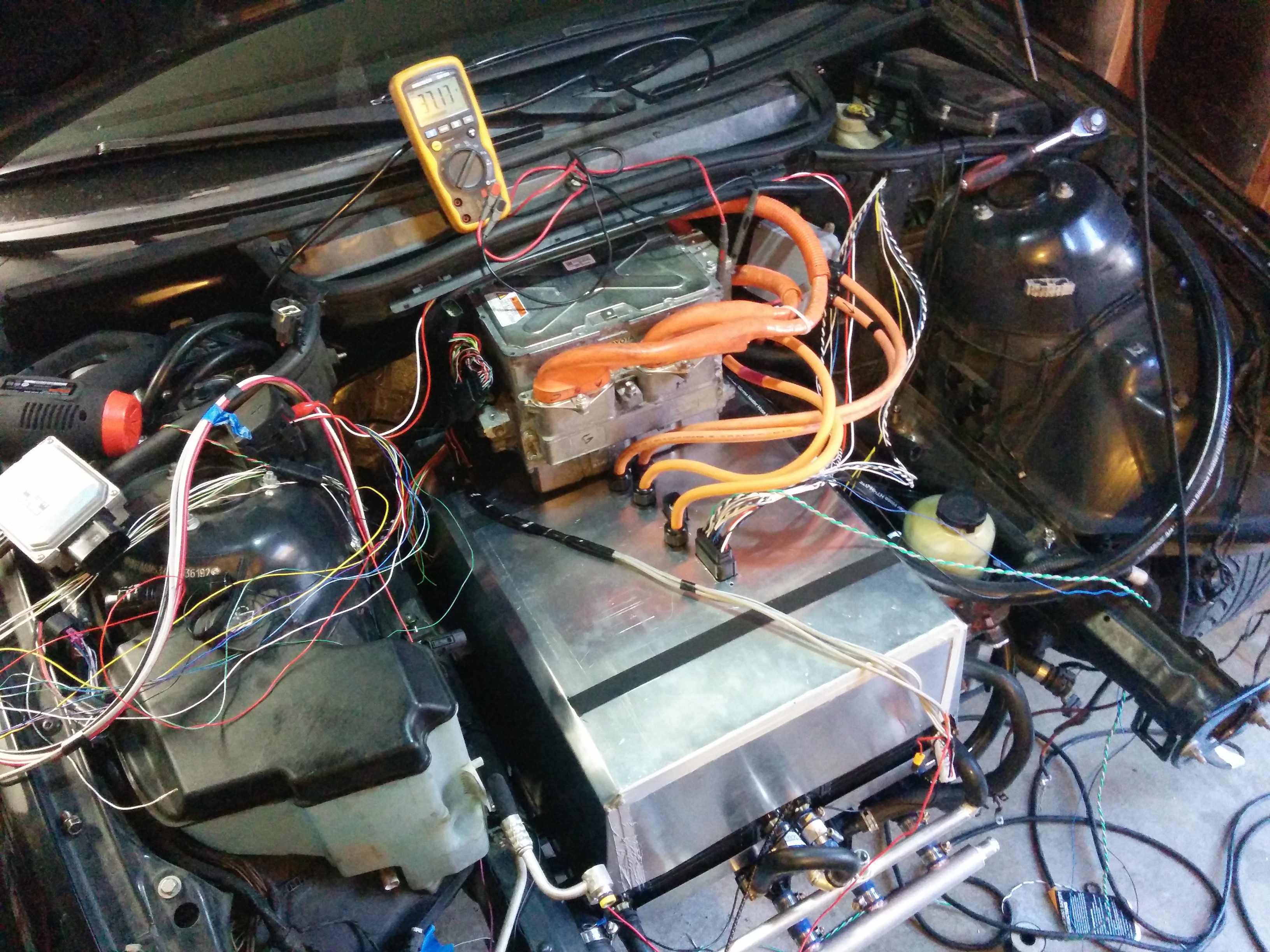
All the components mounted and the cooling system plumbed up. The clear tube is there to be able to confirm flow through the inverter and other power electronics and verify that bleeding of air is complete.
This photo is before any tidying. The wiring is much more organized now, with well defined harnesses routed around the various components.
![]() I made a nice little panel for the top of the front battery. It holds the HV cables as well as the LV logic connections. It makes installing the cover for the front battery much easier than it used to be.
I made a nice little panel for the top of the front battery. It holds the HV cables as well as the LV logic connections. It makes installing the cover for the front battery much easier than it used to be.![]()
-
Reconsidering my inverter approach
10/28/2016 at 04:31 • 0 commentsThe mechanical work is basically complete! I've been running in to trouble with the inverter. Reliable motor control is evading me, as is effective hardware protection. I've blown a few inverters at this point and am taking a step back to reconsider my plan for this final (and most important) piece of the puzzle.
Instead of continuing forward with my own control board, I've decided to try my hand at reverse engineering the communications between the stock inverter and the hybrid controller. I figure that the engineers at Lexus/Toyota, with all the resources and expertise at their disposal, will have tuned the motor control far better that I could ever hope to in my garage. The hardware protections would also be as designed so the risk of blowing an inverter should be much lower than with my amateur attempts at stable IPM motor control. The only way for this project to be reliable enough to act as my daily driver with the occasional thrashing is to leverage the effort already put in to the powertrain in Japan.
To that end, I spend last weekend with a borrowed 2007 Camry Hybrid. This car uses a very similar inverter (same control board inside, right down to the part number!), so I set up my Saleae logic analyzer and recorded the communication between the inverter and hybrid controller while performing a number of maneuvers and taking careful notes.
There is a LOT of data to sift through, but I've managed to isolate the pieces of data which contain the torque commands for each MG, as well as some parts which look like "modes" or "states". I will spend some more time this coming weekend with one of my spare inverters to see if I can manage to get the hardware to respond to these commands. Hopefully I can get away with feeding it the same data I recorded, only varying the torque commands, and have it respond.
DIY Electric Vehicle from Recycled Parts
Converting a car to electric drive using recycled and salvaged EV and hybrid components.


 I made a nice little panel for the top of the front battery. It holds the HV cables as well as the LV logic connections. It makes installing the cover for the front battery much easier than it used to be.