 RodolpheH
Before making my final "Raspberry Shield", I want to experiment with the 433Mhz transmitter and maybe try some experiment with a 433Mhz receiver so I made some sort of "µShield" that will be plugged later on the "Raspberry Shield".
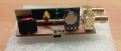 The µShield, ready to use !
This µShield include the transmitter (TX433N), the receiver (RX433N) and 2 SMA connectors for antenas. It has two pins : one for 5V, one for ground, one input for the transmitter and one output for the receiver.
The size of the track connecting the antenas pins from the transmitter and receiver should be a 50 Ohm track. After using some tools on the Internet, I came up with a 2.81mm track.
It also include connectors for a 5V -> 12V DC/DC converter if I want to upgrade the power of the transmitter. Because of this converter (EC1TA02N), I did two separate ground planes. These are connected when not using the DC/DC converter (but I need to add jumpers).
It took one day to design the µShield with Eagle and produce it with my 3020T-DJ CNC. Some mistakes have been done due to a wrong size of engraving bit. I'm using a one-face 0.8mm wide PCB and produce 2 pieces to make a two-faces 1.6mm wide PCB after soldering.
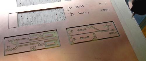
Engraving, drilling and milling with CNC
To get Gcode from my design, I used pcbgcode on Eagle but I had to modify some parts because pcbgcode think that component traces are dimensions and then make the borders thicker. I also cut two pins of the SMA plug because they were too close to the antena's track.
The last design uses a 0.6mm engraving bit (which I find big).
The final µShield had a ground problem (the ground between the two faces weren't connected) so I had to do it myself by soldering the ground plane to the SMA plug (the SMA plug go through the board and is soldered on the ground plane of the other face)
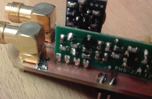
Patching the unconnected ground planes
After making my µShield, all I needed to do is plug it into a breadboard, plug my Pi Cobbler to the breadboard and add some wires. I've added leds on input and output in order to see if signal is received and transmitted by the Raspberry. After plugging my antena on the receiver, It was time to give it a try !
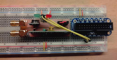
µShield on breadboard connected to the Pi Cobbler
Using yana-server, I was able to control automatic plugs in a range of 20m. I used my SDR dongle in order to measure the signal's frequency and found 433.94Mhz exactly (for a transmitter that output at 433.92Mhz). Not bad ! Better than the remote that is shipped with my automatic plugs that claims 433.92Mhz but output 433.84Mhz
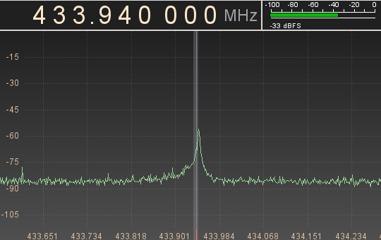
Watching the signal with GQRX
I hope I don't forget anything. Next time I will publish fixed Eagle files and the library I created for the RX433N and the TX433N. Keep tuned, more is coming !
Discussions
Become a Hackaday.io Member
Create an account to leave a comment. Already have an account? Log In.