Quick update:
.) Home made rheoscopic fluid works
.) The driver board satisfies all system requirements
.) New hardware, new board design is coming along
.) Fixed an issue with board current on USB connections
.) Fixed an Arduino Nano windows driver problem
.) Hope to try making ammonia "real soon now"...
Home made rheoscopic fluid
Finely ground mica mixed with water makes "rheoscopic fluid" which shows currents and eddies in swirling water. Powdered mica is available in the makeup section of eBay in various colors.
The result is a sort of silky, swirly mixture that makes long lines that follow the current patterns. It's hard to explain, but there's lots of images on google that show the effect.
I only used a tiny amount of mica because I wanted to keep the water transparent. The fluid works, I can see the current patterns, it just wasn't very informative.
Ah well - this is science. I suppose this is an example of "Hackaday Fail". Still, the home made rheoscopic fluid seems to work well enough.
Board works, all requirements met
As mentioned in my previous log, the new board is stable up to 150 watts.
Some things could be improved (I have a list), but in its current state the board satisfies all design requirements for the project. I could use it as is, or cautiously make some upgrades.
I have 4 hardware improvements that should be straightforward. My plan is to get these working on a proto-board, then do schematic capture and and have PCBs made.
Too many chips, not enough power
A standard USB connection can supply a maximum of 100 mA of current. The AD9850 sine generator requires 76 mA, and the board also has an Arduino, an FT232 converter, and at least 2 power LEDs.
So it came as no surprise that the components were struggling with the limited amount of power available.
The solution is to power the circuit from the ATX 5V line, and of course the "smart power circuit" on the arduino board will have none of it, so the quick solution is to cut the red wire on a USB cable.
The cheap Chinese knockoff Nano "smart switch" circuit doesn't work well. I can't run the 12 V line to the arduino onboard regulator either, but I may not need it - see below.

Nano windows driver problem
The Arduino Nano windows device driver was causing a lot of problems.
With the Nano sending output to a serial window, after awhile the mouse would go wild - the pointer would move and select things seemingly at random.
The only way around it was to reboot the computer, at which point you would get another hour or two of development until the mouse went wacky. This hampered development quite a bit.

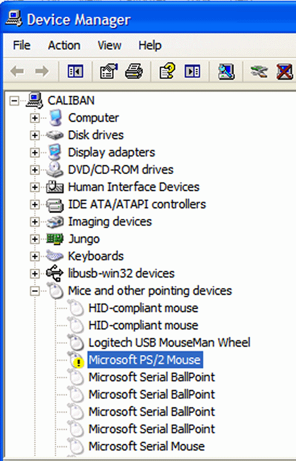
I finally discovered the cause: the system identifies the serial port as a microsoft mouse product, so in addition to being a serial port the device was being installed as a mouse!
This is a problem with the Chinese knockoff driver CHSER340.exe. I can't find Nano's with real FTDI chips any more - nowadays everyone uses the knockoff USB interfaces.
The solution is to disable the unwanted mouse in the hardware manager. Assuming you don't actually *have* a "Microsoft Serial Ballpoint" or other serial mouse, this should fix the problem.
It turns out this is a known windows problem.
AD9833 is cheaper and simpler
One of the 4 proposed improvements is to use an AD9833 sin/square/triangle generator, which only needs 5 mA.
Additionally, the squarewave output reduces the component count and complexity of the circuit: a single XOR can turn the squarewave into short pulses needed by the UC3525 PWM chip, and double the frequency which is *also* needed by the UC3525 PWM chip.
Curiously, a development board on eBay costs less than the chip itself.
Specifically, the AD9833 chip costs $10 on DigiKey (quantity: 1), but a breakout board with the chip, a 25 mHz crystal, and decoupling capacitors is only $6.99 on eBay. Go figure.
If I use the dev board as a component, this reduces cost and reduces the number of SMD components needed to assemble the board! The interface is a line of standard 0.1" pins, which are trivial to solder.
UPDATE: I've got a software driver, the chip seems to work, so I'll include it in the final version.
And way accurate
I've been checking the generated frequency against a calibrated frequency counter, and the results are exactly right.
And I mean exactly - each generated frequency measures exactly the right value on the counter, with no error!
 Peter Walsh
Discussions
Become a Hackaday.io Member
Create an account to leave a comment. Already have an account? Log In.