 Andrew Mayhall
Lets start off with the unsuspecting subject that will serve as the organ donor for this Franken pump project. The Pacific Hydrostar 3/4HP clear water pump

I picked this bad boy up from Harbor Freight about 2 years ago for a parts washing station. If I recall correctly I think it cost about $50 - $60 new. Unfortunately, I never got around to building the part washing station so it has been sitting in my parts inventory forever.
Now that I have an upcoming project needing a pump of sorts, this is the perfect excuse to use it!
The pump is pretty basic... Cast Iron construction, split phase induction motor 1" NPT inlet and outlet connections, etc.
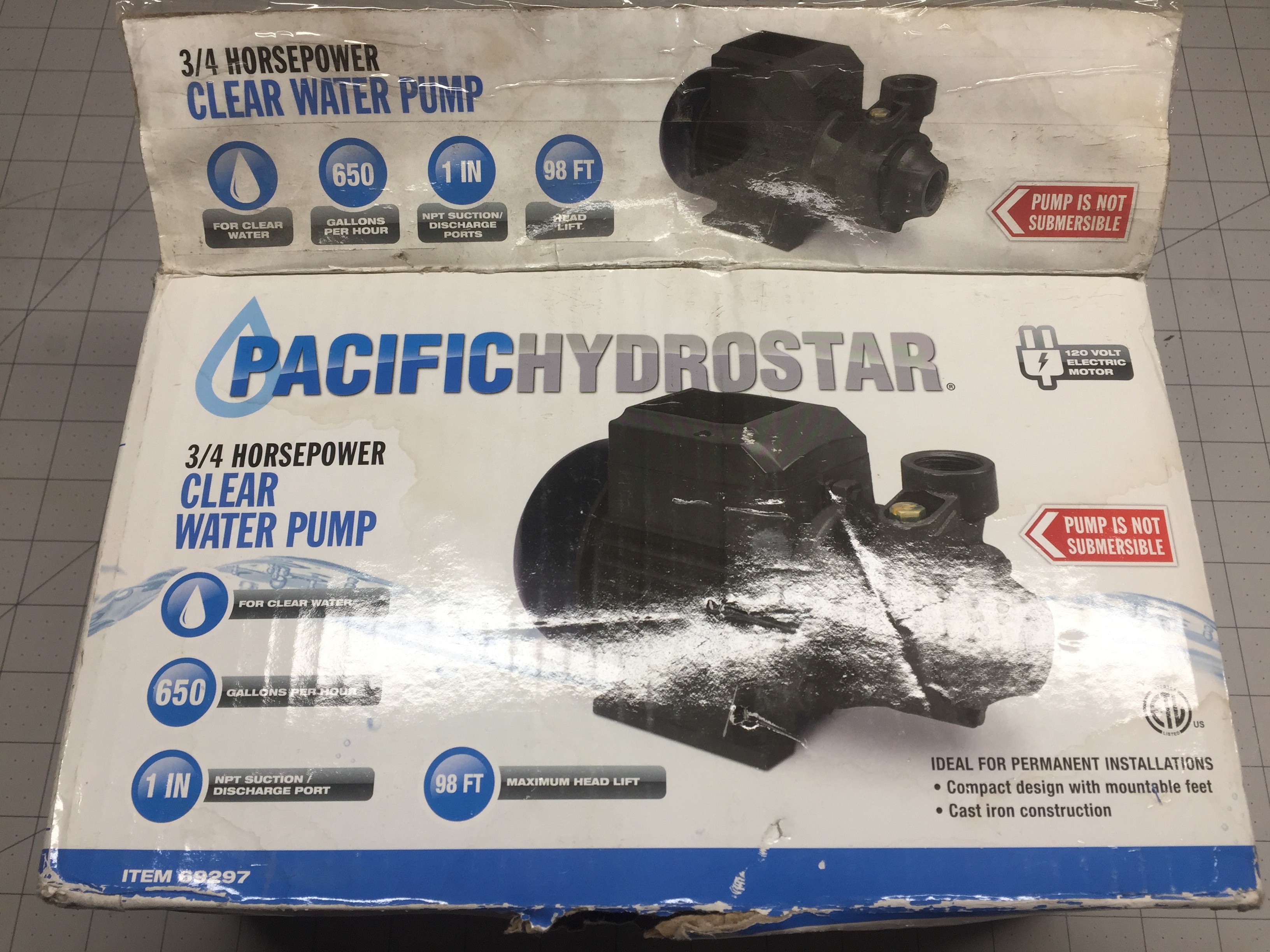
The box advertises 98ft of head, and 650gph nominal. 98ft of head works out to be around 40psi. Surprisingly, unlike most Harbor Freight items, this marketing wank is pretty on par and perhaps a bit low. But I am positive we can do better!
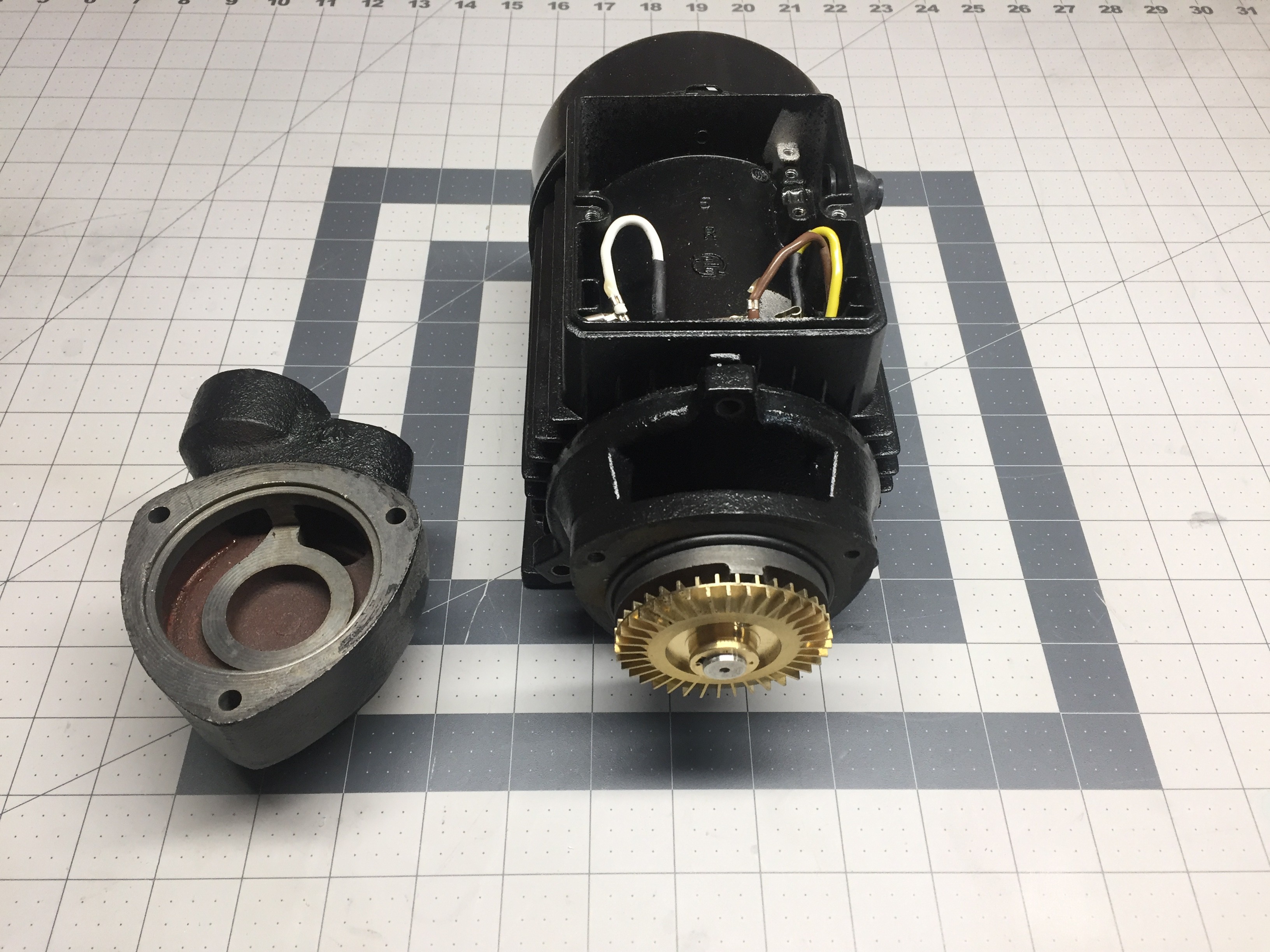
Above, I have disassembled the casing to get a good look at the impeller which has no forward or backward curvature but rather perpendicular paddles.
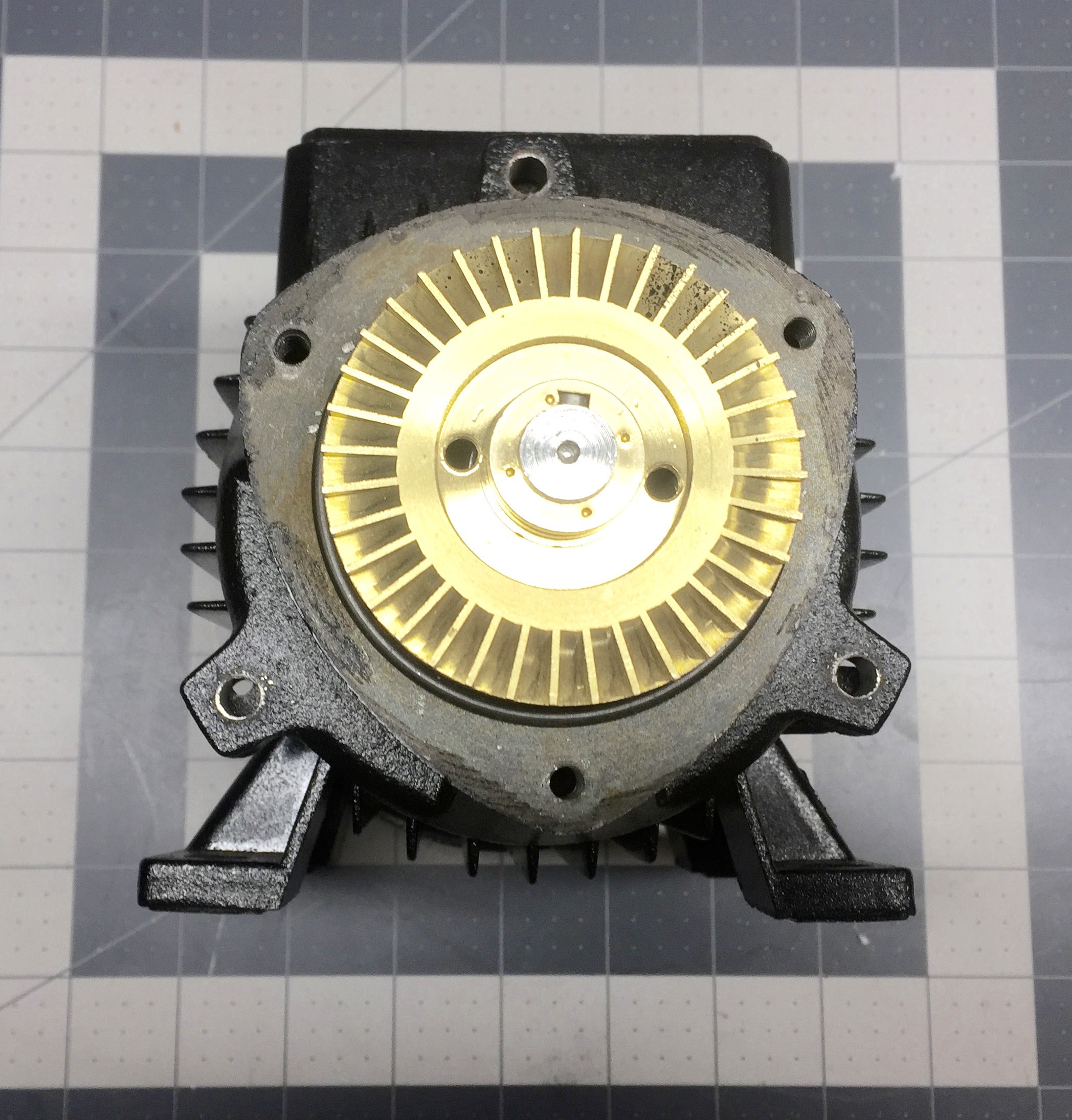
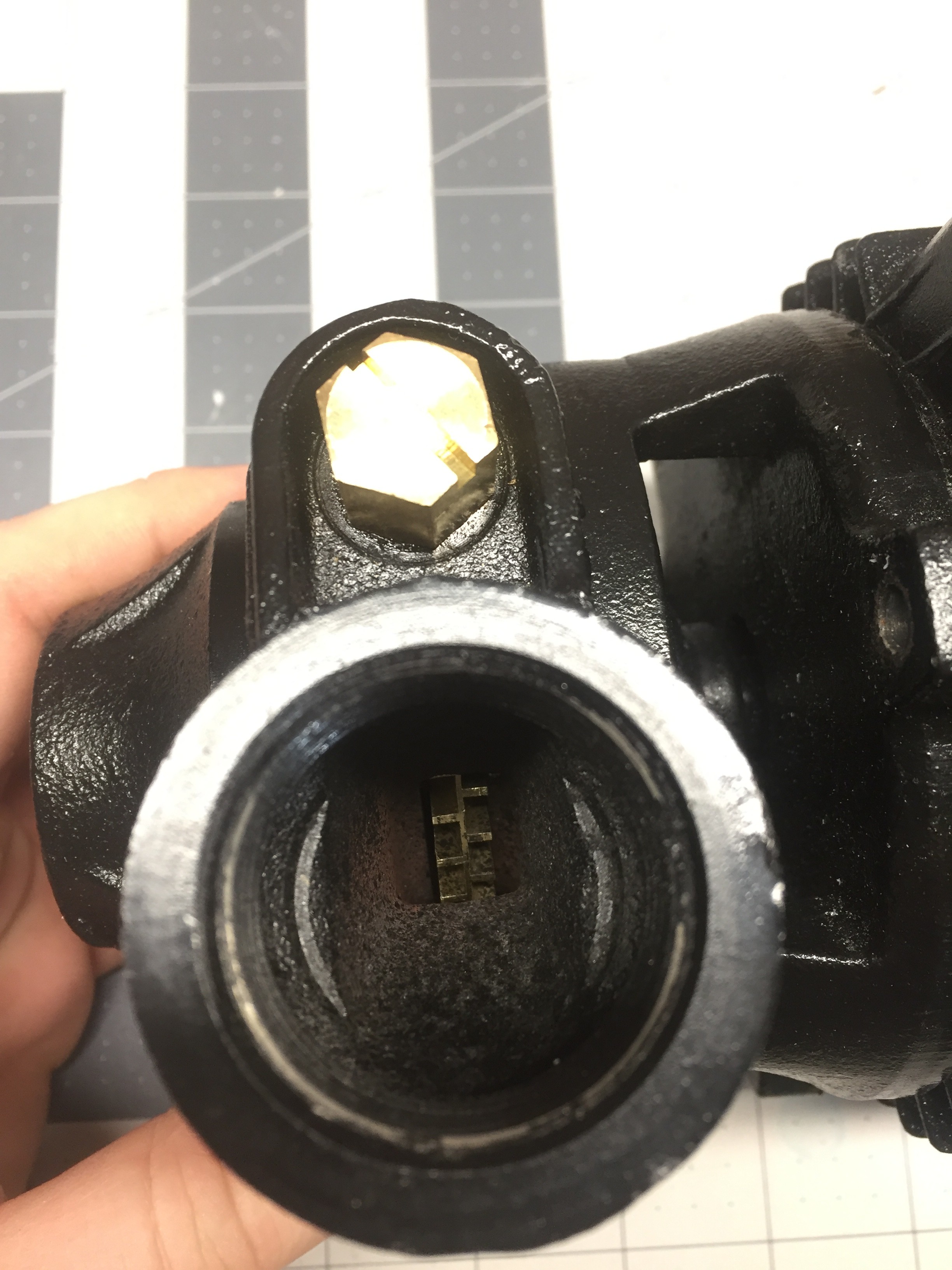
The impeller doesn't follow the traditional design of a centrifugal pump as the intake is actually routed to the perimeter of the impeller.
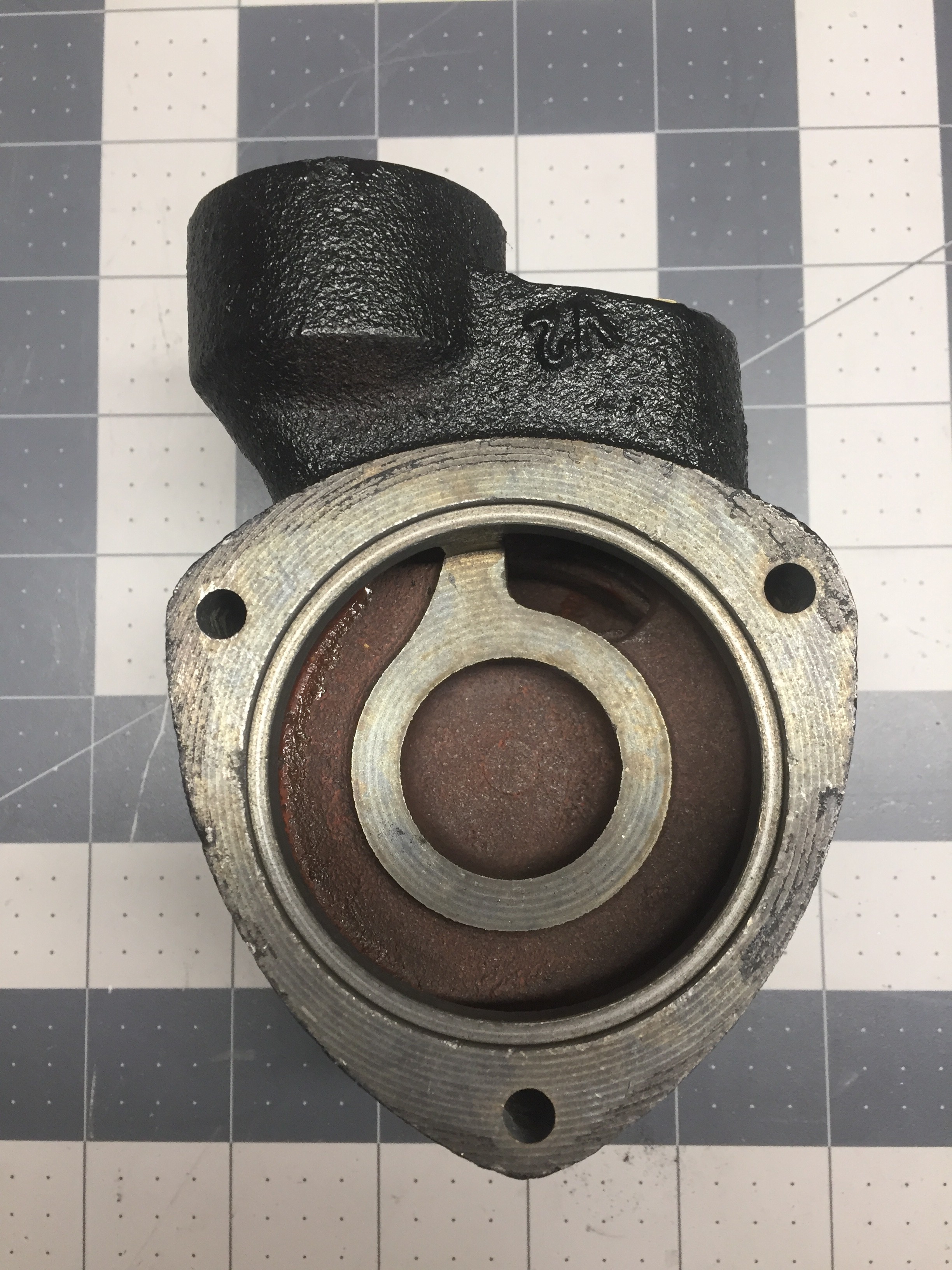
To my surprise the volute casing of this pump is rather constant and it appears to move water by brute force thus making me believe cavitation will likely be an issue with this impeller design...
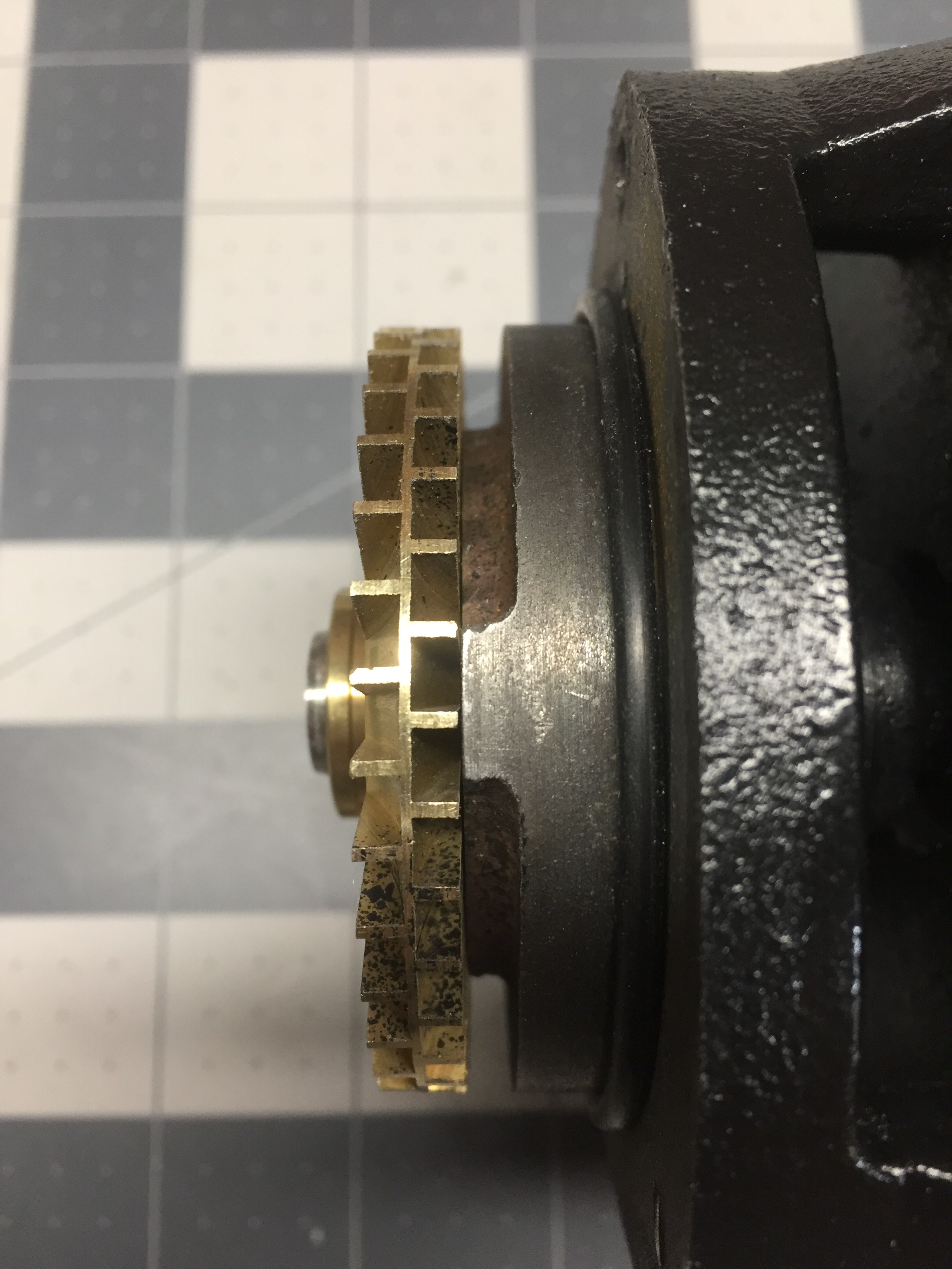
The impeller is sandwiched between two halves of the casing with a cutwater separating the intake from the exhaust. As the water enters the intake it is routed to the volute where impeller is spinning at around 3600RPM. The perpendicular paddles force the water to the outside of the volute as well as imparting some angular momentum into the water. The speed of the impeller and centrifugal flow helps to force the water around the volute casing and up to the cutwater and thus out through the exhaust.
It is honestly surprising that this pump is able to generate 60+ psi of pressure. At higher impeller velocities cavitation will most defiantly be an issue. Should offer up an exciting aoitoposy at a later date!
Anyways! Carrying on with the teardown....
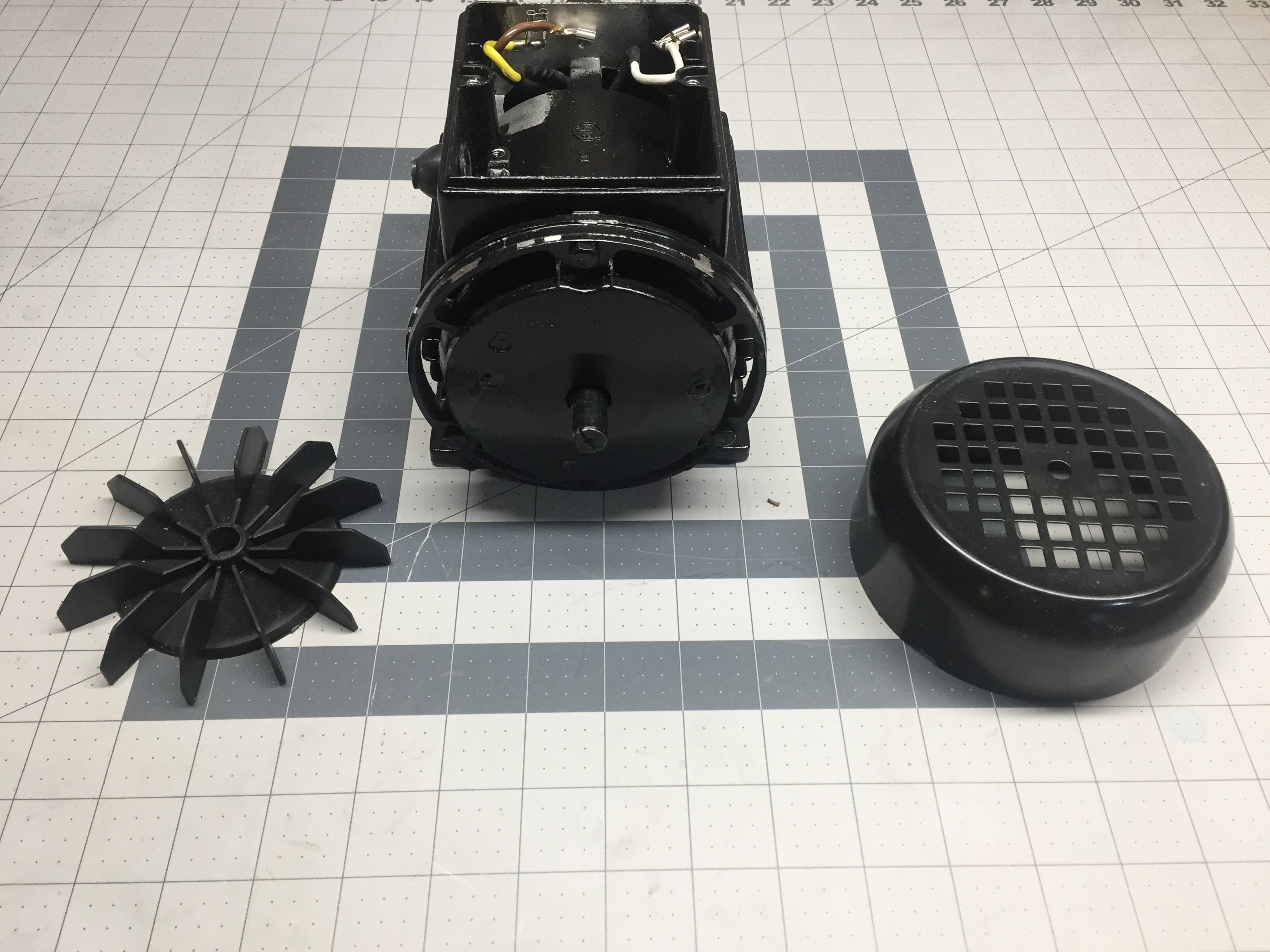
The fan housing is just friction fitted to the back of the pump... Scratch off the paint and you won't get it to stay in place!
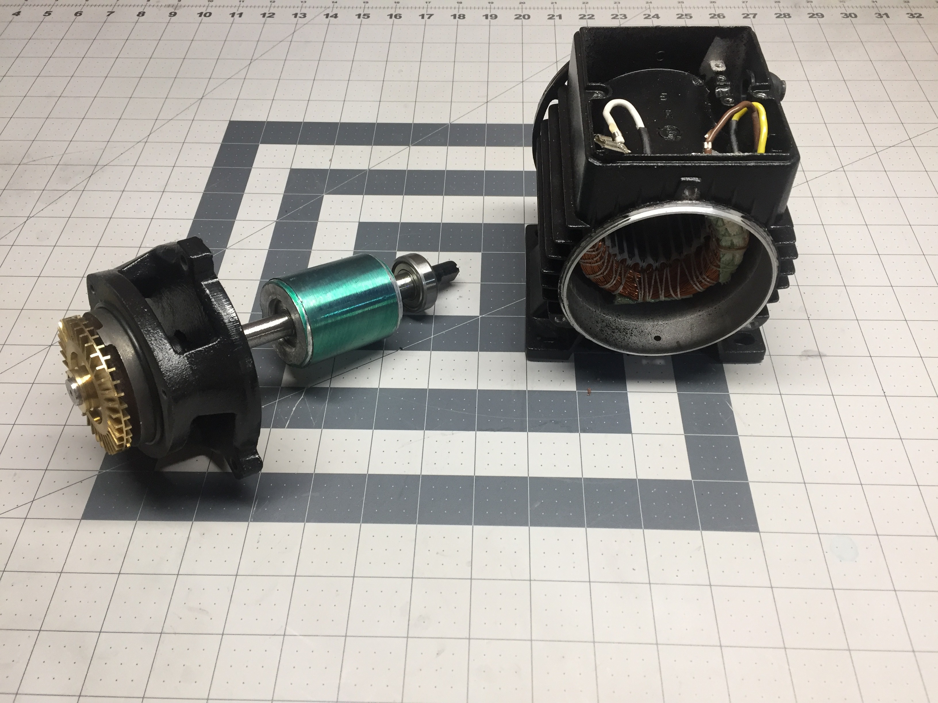
Lovely motor armature, ready to be cut off and thrown to the side!
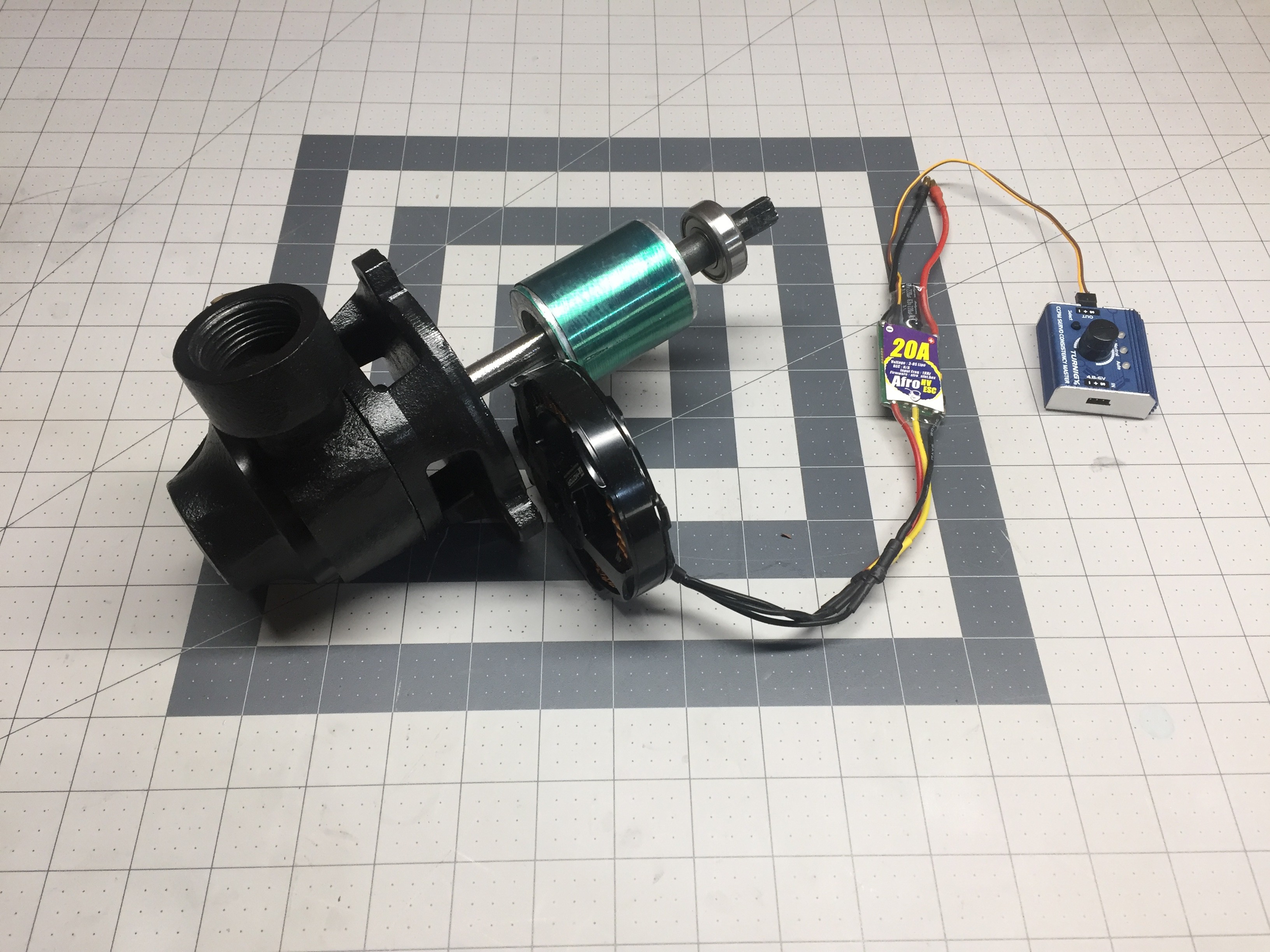
The plan is to cut the motor armature off and toss it aside along with the stator. I will need to build a new housing to mount the BLDC motor and come up with an adapter to couple the new motor to the shaft of the impeller. This sounds like an excellent job for 3D printing!
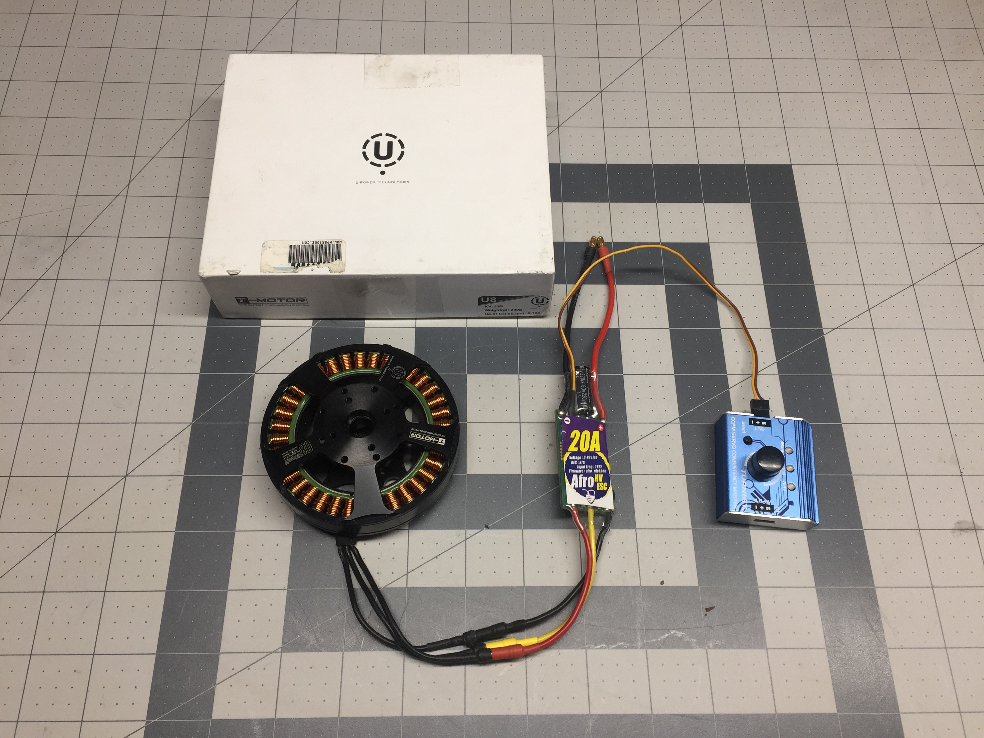
My motor of choice for this project is a T-Motor U8 - 135KV. I have 4 of them that I picked up good two or three years ago at an online auction for really really cheap. Market price has them around $180 a piece.... Now, hopefully everyone understands why not to build your own variable speed pump! - At least with theses exact parts that is!
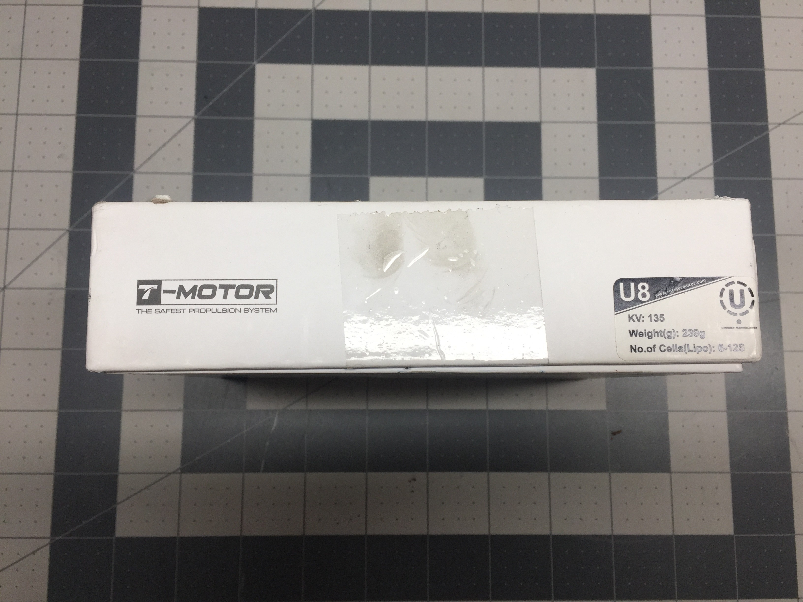
The specs for these motors are pretty good:
310w maximum continuous power at 48C
24v to 50v.
14A max current at 24v
So, to match the pumps volumetric output, I will need to get close to 3600RPM which should be around 26v. - Totally doable.
A simple 20A controller should suffice but I do have a few 30A ones and a 80A that is programable and communicates with I2C that I may experiment with.
In the next log, I will go over the 3D designs and order the prints!
Thanks for checking out this project! Hope you enjoyed and will follow along in the next update!
Discussions
Become a Hackaday.io Member
Create an account to leave a comment. Already have an account? Log In.