 cselzey
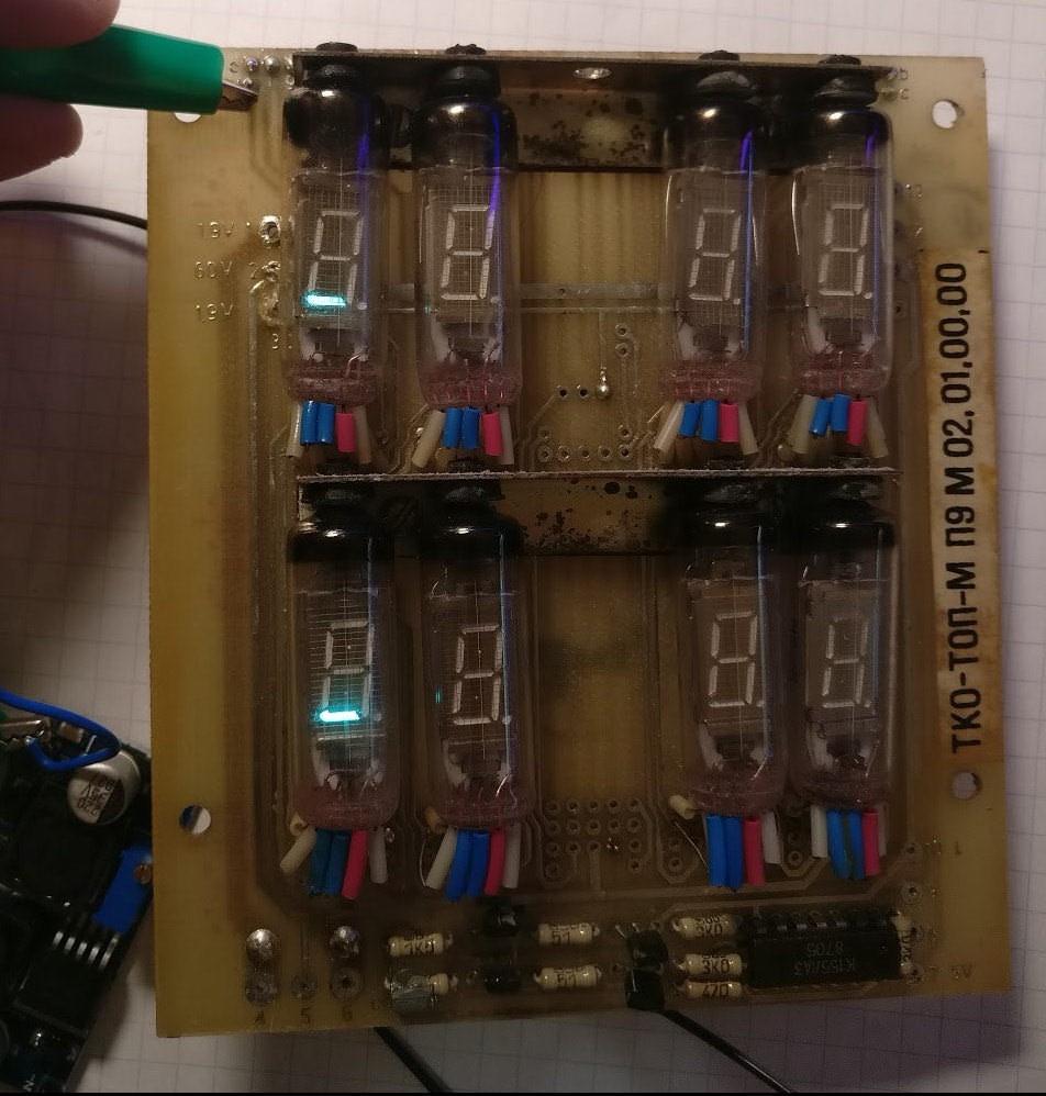
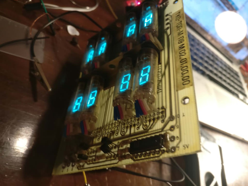
Spoilers: Here is what the end result looks like! I can't get enough of that steel blue glow of the VFDs. I'm a huge fan of vintage display technologies (Nixies, Numitrons, split flap, you name it) and will take this beautiful piercing blue glow over boring old LED modules any day.


Found a bunch of these interesting looking vintage surplus VFD-tube display boards on eBay a few months ago. They were pretty cheap, so I bought a few and thought I'd try hacking them back to life. They still come up for sale from various sellers and after my experience completing this project, I'd recommend picking one up if you love tinkering.
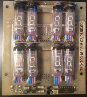
Wow, these boards look awesome! Quite unlike anything that's been produced in many years.
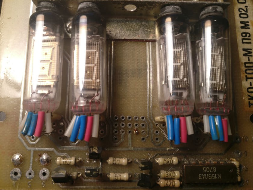
Two transistors, a mystery chip and a few resistors are the only components on this board. Clearly the bulk of the circuitry for driving the tubes was located on a separate board.
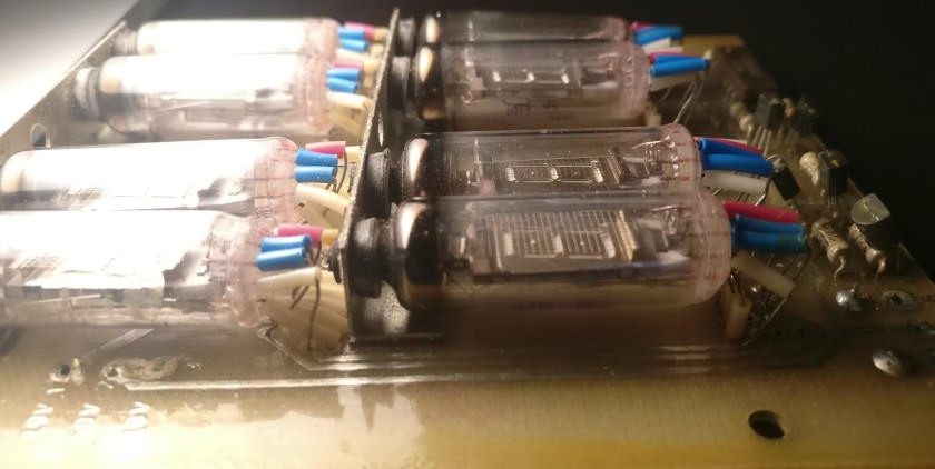
This really does appear over engineered by today’s standards. Note that the designers went through the effort to create a custom metal bracket with holes to fit the nipple of the tubes. A rubber grommet protects the fragile glass against vibration. Also, it is clear that a lot of tricky hand assembly went into the manufacture of this board, with the way the tube leads have been insulated with loose plastic sleeves and precisely bent to line up with the footprint on the board at a right angle.

The tubes themselves are actually fairly remarkable feats of mass-produced engineering as well, each containing many tiny metal parts assembled together and sealed in a glass envelope. Compared to today’s ubiquitous LED modules, this almost looks like alien technology. The board uses the fairly common IV-6 tube. I actually have about a dozen of these bare tubes in my parts bin, but have yet to incorporate them into a project.
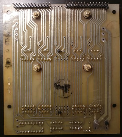
A stamp on the left side of the back of the board gives a manufacture date of 1987. I would have thought LED displays would have been in use by then, (which would have greatly simplified the design of this display module, whatever it was used for,) but perhaps this was still the most cost effective or reliable approach at the time. Or some engineering house in the USSR just got stuck with a huge overstock of outdated tubes and needed to get rid of them somehow. The back of the board reveals that many of the connections on the two tubes in each column are grouped together, meaning that the display was designed to be multiplexed four tubes at a time. I also took the opportunity to solder a row of male header pins to the top of the board, as the connections on the board conveniently had 0.1 inch spacing.
To reverse engineer the board and determine how to drive the tubes, I probed around on the board until I located the filament connections, which were conveniently labelled “1.9v.” All the filaments are connected in parallel. I applied about 2 volts to these points with a bench power supply, set another power supply to 24v, and connected this high voltage to what I believed was the separate grid connections for the top and bottom rows of tubes. I then touched the top header pins with 24v, and the segments lit right up! As I expected, the display is intended to be multiplexed in a 2*4 configuration, illuminating the top and bottom rows alternatively.
The circuitry at the bottom of the board appears to be for driving the grids for the multiplexing operation. Pulling the grid connection of the bottom row low and the one for the top row high would cause only the top row to illuminate. Rapidly switching between lighting the top row and the bottom row gives the illusion that all eight of the tubes are steadily illuminated. It seems these boards were intended to be daisy-chained together to be multiplexed off the same segment control line.
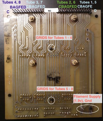
After probing around some more, I have a complete pinout of the board.

Now that I have the display board reverse engineered, my first instinct is to turn it in to a clock! Since the board fits standard .1 inch header pins at the top, I thought it would be fairly easy to attach a custom PCB to the original board. I wanted to cram enough of the necessary circuitry onto the new PCB to limit the number of external modules that would have to be wired to the board. I wanted the PCB to include the following:
- VFD Segment and Grid Drivers (Ideally as a single IC)
- 24v, 5v, and 1.9v voltage rails (for the segment/grids, logic, and filaments)
- Onboard microcontroller
- Real Time Clock IC for accurate timekeeping
- Buttons for setting the time
- Power input
I researched various methods of driving large numbers of VFD tubes, and it became clear that using a specialized VFD driving chip would be well worth the cost and effort of obtaining one. 28 segments and 2 grids need to be driven. I eventually decided on the Maxim 6934 32-output VFD driver, as it was one of the few available that had enough outputs. The above highly technical block diagram make on a very early build of DaveCad™ is what I used as a guide when setting off on creating a custom PCB.

MAX6934 datasheet. The downsides is that it is only available in a PLCC or a QFN package, which rules out hand soldering or breadboarding. I didn’t consider this an issue. PLCC-44 to through hole adapters are cheaply available, so I ordered a few of those. This rules out breadboard prototyping though, so I hope I get the pinout right on the PCB!
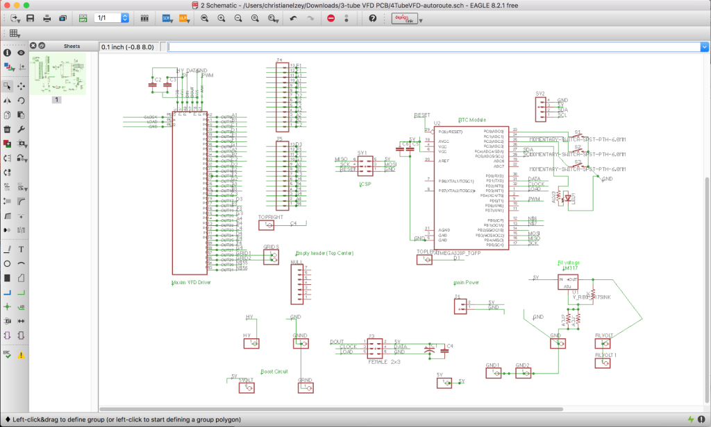
To give the clock some brains, an ATMega328 AVR microcontroller was included on the board, as well as 3 pushbuttons for setting the time and date. The ATMega328 is more than capable of controlling the clock, and may even be overkill, but I already had a few in SMD form I was looking for an excuse to use, so it made it on the board design. To allow for more precise timekeeping and battery backup of the time, a DS3231 real time clock module was connected to the microcontroller. I already had plenty of these left over from my Numitron clock kits https://imgur.com/a/EQdnd
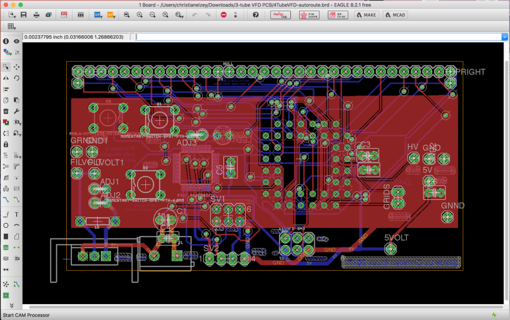
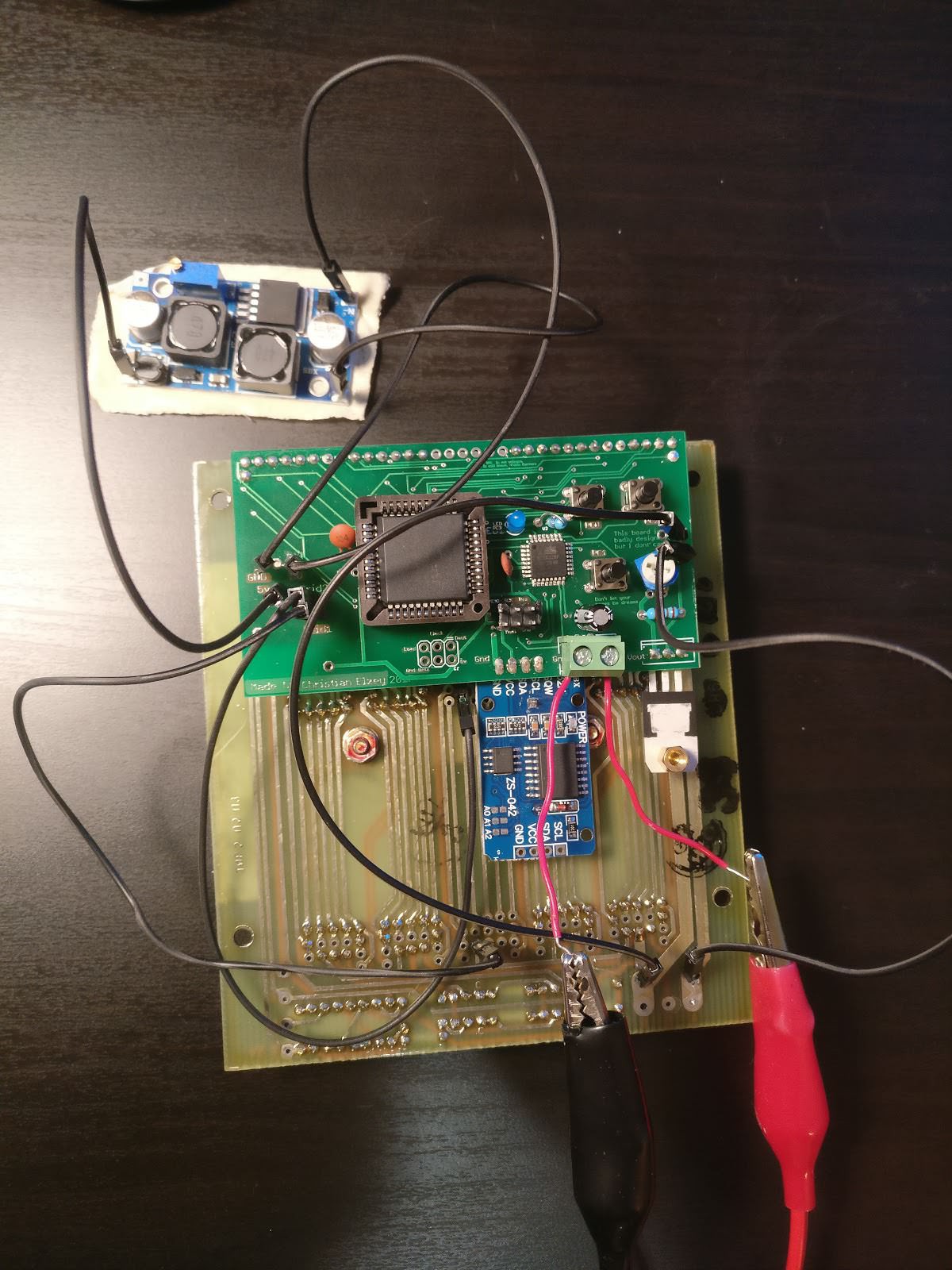
Not my first board layout, but it is likely the most complex one I've ever done. (I'm new at this, let me know if you see any major design no-no's.) I designed the new board to fit tightly against the back of the original board without being visible from the front. Most of the connections between the boards are made through the header row at the top, although wires for the grid and filament interconnections would still be necessary. Also, the boost module supplying the 24v rail is not mounted to the custom board, and is simply to be attached with three wires.
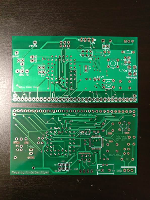
It’s always exciting unboxing PCBs you have waited so long to get. They look great! Also, I discovered how challenging it can be photographing shiny circuit boards without getting any glare. And then I Noticed a mistake. The ICSP programming header for the AVR microcontroller is wrong. Oh well, could have been worse. I'll deal with that when programming time comes. Time to start assembly!
I started by soldering on the ATMega328 microcontroller. I am not the greatest at SMD soldering, and did not want to risk ruining a otherwise complete board with a botched SMD job.
I found that clamping the board to my desk and individually tack soldering the leads of the component work best for me. And it is good that I started with the MCU, because I ended up ruining both the PCB and the chip on my first attempt. That’s what spares are for, right?
After installing the LED and a few other components, I hooked up my USBTinyISP programmer to the board and flashed the chip with a simple blink program. A blinky light means the micro survived installation.
Skipping forward a bit, and the assembly of the board is done! Now to test it out...
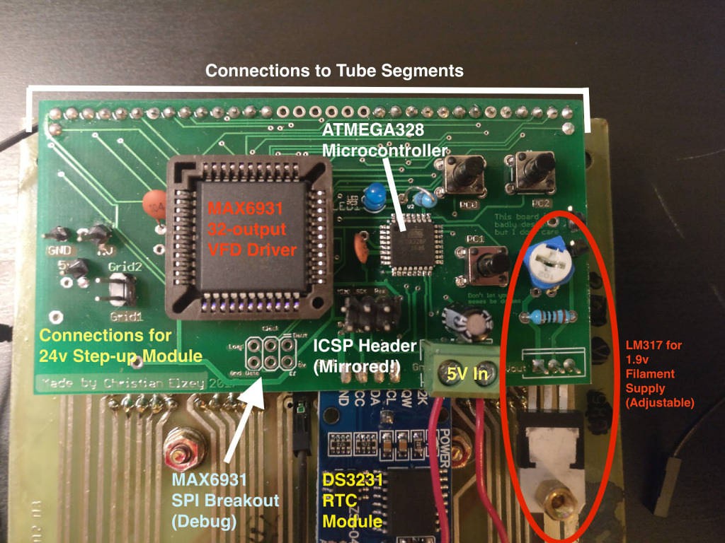
(The large chip is actually a MAX6934, not the MAX6931, and the connections to the tube grids are not visible.)
I actually assembled two controller boards as I had enough components. This came in handy after I bricked the microcontroller on the first board I assembled! While editing the internal settings on the microcontroller that control the clock frequency among other things, I accidentally disabled the reset pin, preventing further programming of the chip. Whoops! This board is now useless in its current state. Sure am glad I had a spare board! It turns out it is possible to rescue an AVR stuck in this state by zapping it with a high voltage programmer, but I do not have access to one of these. I’ll hang on to this board so I can bring it back to life in case I ever get a hold of one of these programmers.
The other controller board that still has a functional microcontroller I ended up soldering directly to the tube PCB. Hoping nothing goes wrong with this one! This is what it looks like when installed, with components labelled:
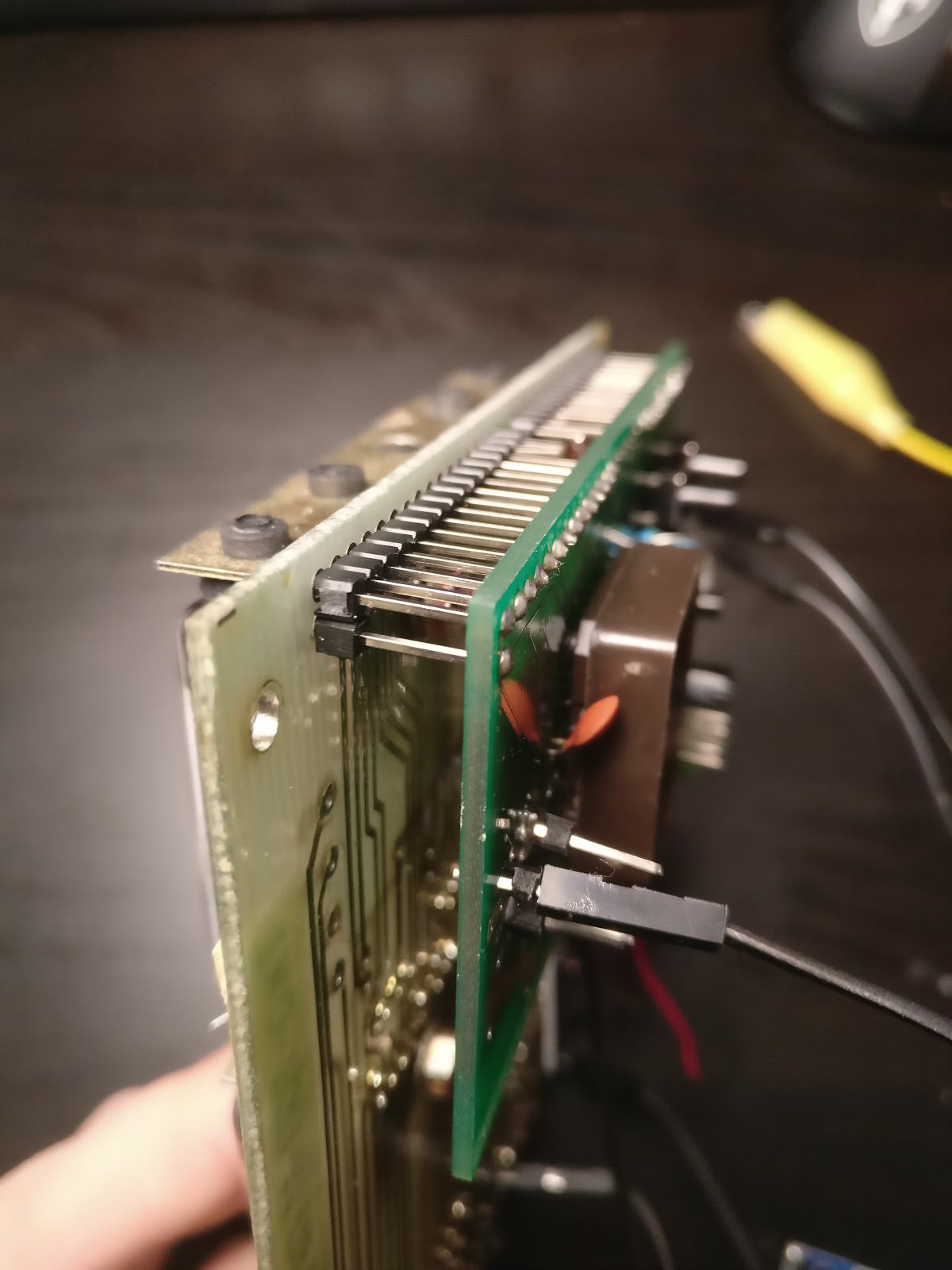
How my custom PCB fits right behind the original board.
Success!
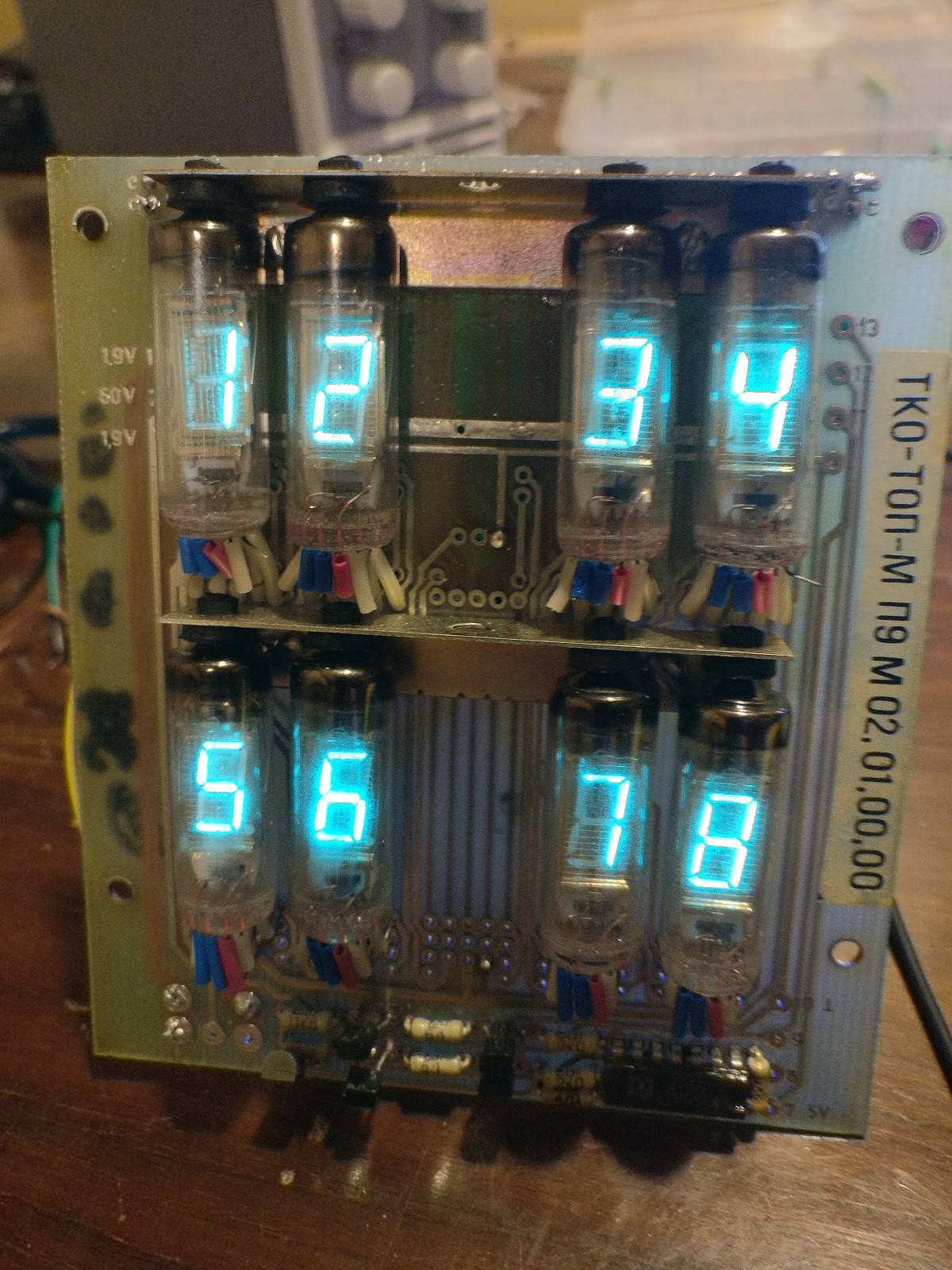
Success! Getting full individual control of the tubes took a bit more work, but works very well!.
The next step was to write the code to turn this into a clock with date display! For this, I decided to ditch Arduino and program the ATMega directly in C using only the standard AVR library and header files, and flash the chip using AVRDude and a cheap eBay USBTinyISP programmer. The code ended up being a bit "hacky" but it works! The time is read from the DS3231 RTC over I2C, and the time is displayed on the top four digits, and the date on the bottom four. The buttons on the back are used to set the time and the date, and the blue LED on the back of the board lights up to indicate PM time. (it can only be seen when setting the clock really). And that's it.
No external libraries were used, but the code for I2C communication was inspired heavily by Bruce E. Hall's tutorial on adding an RTC to an AVR project, over at /w8bh.net/avr/AvrDS1307.pdf.
Update: over 8 months later of 24/7 use, the clock is going strong, and keeping great time! The VFD tubes look just as good as they did when they were first brought back to life. I don't doubt that they will last many, many years.