 Matt
MattHowdy!
I have a new board completed! This my first USB enabled device I've made, a programmer for the ESPLux. Really, it is just an FTDI chip with a 3.3v regulator on board, with a pinout that suits the ESPLux programming header. I think I need to play around with the location of the temperature probe in my reflow oven, I don't think the board quite got hot enough .. I'm still learning this reflow soldering thing.
Here is a photo:
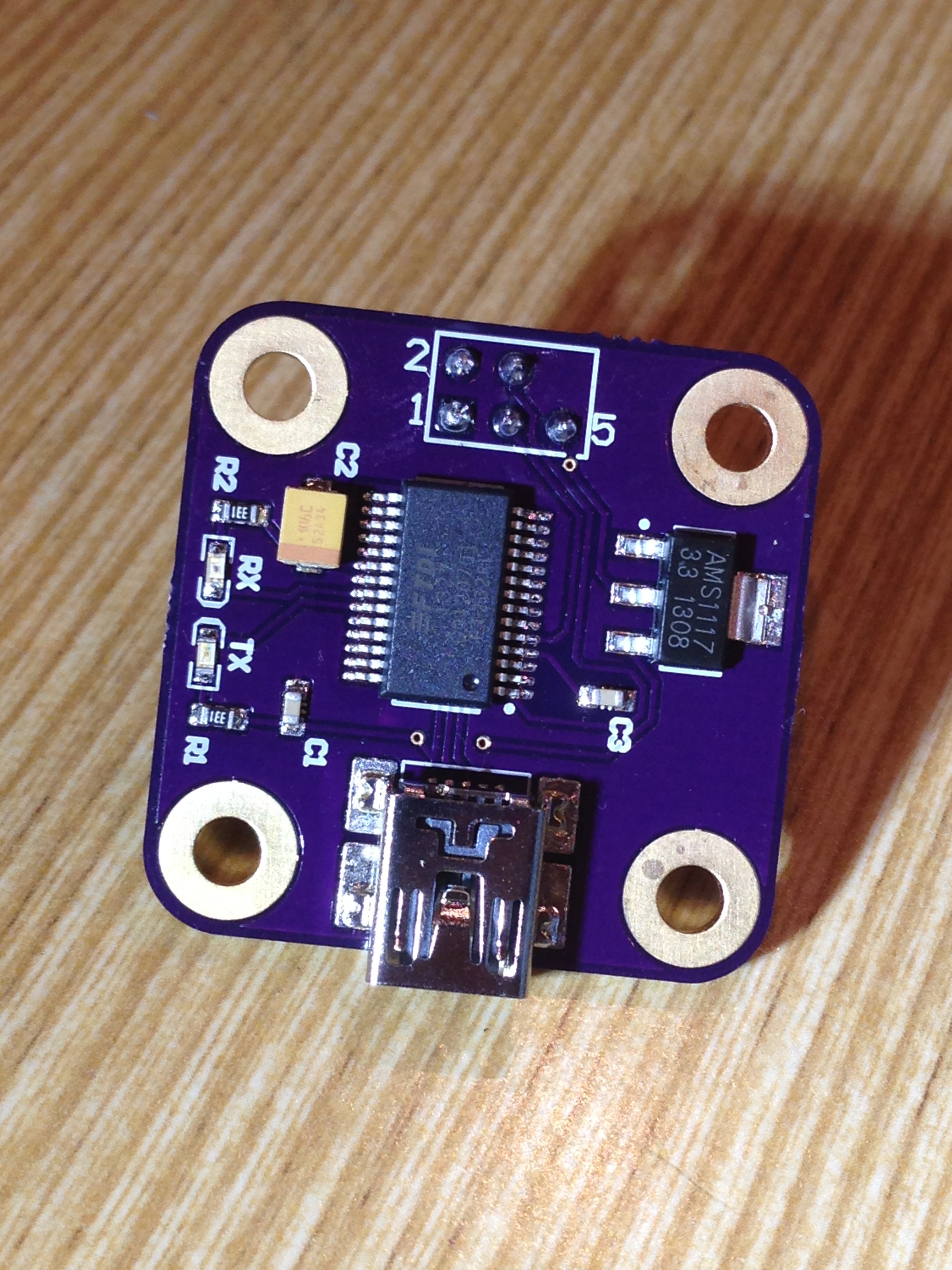
It looks like my beginners luck is slowly running out. There are two mistakes on this board. First, I forgot to check for airwires before sending the board off (fail) and missed that one of C3's pads doesn't actually go to ground. I placed a copper pour over the whole board, and up until this board, and the ESPLux board, it has covered every pin that I need. Lesson learnt! Copper pours aren't a magic routing bullet!
The second mistake was that the holes I put in for my pogo pins aren't big enough. I knew this, and it completely slipped my mind. I just wanted to use up some of my OSHPark credit!
In any case, C3 seems to not be a requirement for the board working, it just looks like a filtering cap. Worst case, I'll chuck in a bodge wire to get it working.
The fail with the pogo pins has kind of turned out in my favour. Here's what I did (sorry for the poor focus, my phone doesn't like doing macro shots):
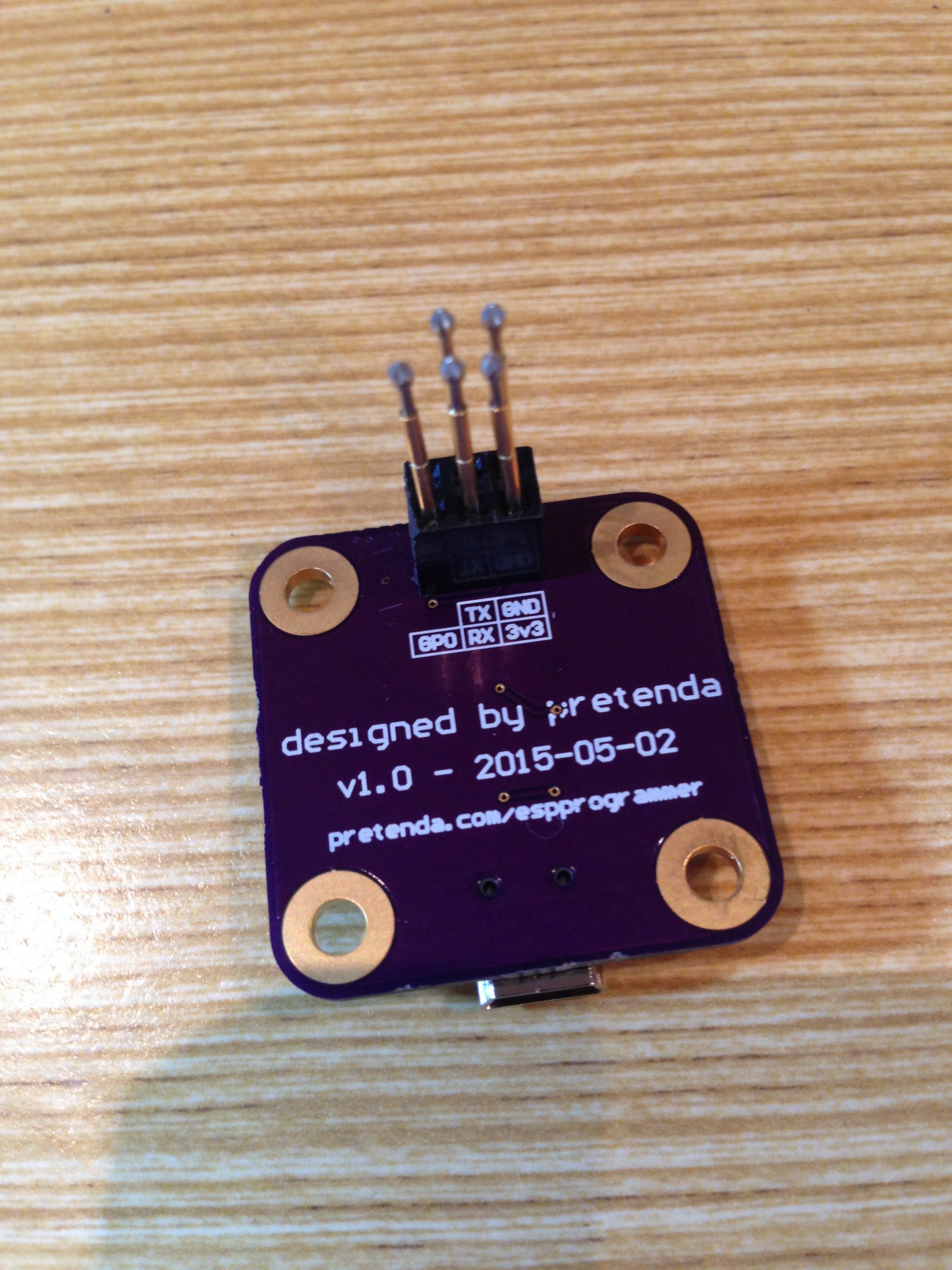
I ended up mounting a 2.54mm female header block on the board, and then drilled out the holes in the plastic to 1mm. This lets me fit the pogos into the header block, and an added bonus is I can pull the pogos out, and use it as a standard 2.54mm header. This means for my first ESPLux, I can use the same boards, solder in a 2.54mm male header and work without having to hold the pogos in place.
I thought I should go through a little bit of background on the pinout for you. I have explained this before, but I may as well explain it here alongside the pictures of the finalised board. Pins 1-4 are pretty simple. It includes ground, 3v3, TX and RX. The 5th pin is where (hopefully) things get a little bit more exciting. On the ESP8266, for normal operation, you need to pull GPIO0 high (in other words, join it to 3.3v). To program it, you need to pull it low (or join the pin to ground). On the ESPLux board, I have put a 10k resistor between GPIO0 and 3.3v, and then ran a trace for GPIO0 up to the programming header. On the ESPProgrammer, the 5th pin is connected directly to ground. This means when the programmer is connected, GPIO0's path of least resistance is to ground, which puts the ESP8266 into programming mode when the header is connected. In hindsight, I probably should have put a jumper on the top of the board so I can easily enable to disable this feature, but in the grand scheme of things, it probably won't impact me that much. I can always pull out the pogo if it becomes an issue.
In any case, the ftdi chip works! I have yet to see if the functionality I described above works, but when I get the boards from OSHPark I give it a shot.
Edit: This also means I can now start working on my firmware again! Here's hoping for an update on that soon.
Discussions
Become a Hackaday.io Member
Create an account to leave a comment. Already have an account? Log In.