 Duane Degn
I was very surprised to find I was selected as one of the 100 semifinalists for the 2015 Hackaday Prize. I've been busy as time allows trying to flesh out the design of my robot.
One concern I had way the way the unpowered sprocket connected to the chassis. I had previously used a blind nut and bolt and allowed the sprocket to rotate on the bolt.

The blind nut can be seen in the right side of the above photo. I had attempted to heat the blind nut up in order to set it into the ePVC (expanded PVC aka foamed PVC) more securely but I ended up burning the plastic in the process.
I wanted some way of securing this sprocket so it could both freely rotate and I wanted the position of the sprocket axle to be adjustable in order to modify the tension of the treads.
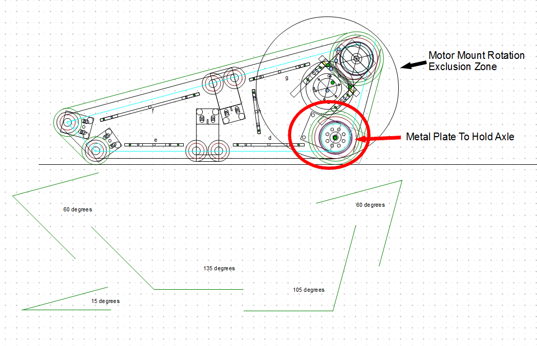
Here's a revised drawing of the tread support structure (the drawing includes the angles made by the tread).
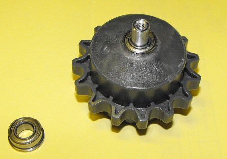
Here's a photo showing the actual parts to be used.
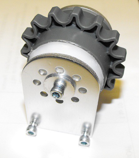
These metal plates were purchased from ServoCity. I used ServoCity's 1/4" standoffs (1-1/2" long) as an axle.
These metal plates should allow the axle's position to be adjusted but I didn't want the plastic wheel to rub directly against the axle. I considered having the axle solidly attached to the sprocket but I finally decided to drill the sprocket out larger than than axle and add bearings to the sprocket.
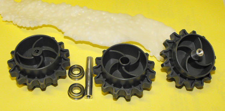
The sprocket on the right had a hole drilled just under 1/4" and then the standoff/axle was forced through the hole. If I had used this configuration, the bearings would have been placed in the tread structure. I thought this configuration introduced to many problems since the screws which would thread into the axle would need to rotate with the wheel.
I decided rather than drilling an undersized hole, I'd drill an oversized hole and add bearing to the sprocket.
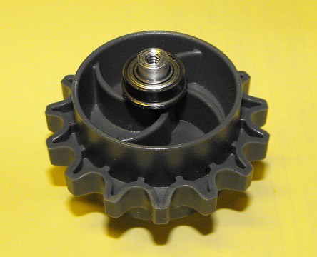
To hold the bearings in place I used Polymorph.
The Polymorph is still hot and clear in the photo above. Once it cooled it looked like this.
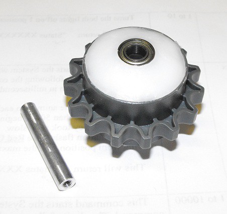
I think it looks pretty cool.The flange on the bearing helps to hold the bearing in place.
With bearings added to the sprocket, the axle no long rotates with sprocket.
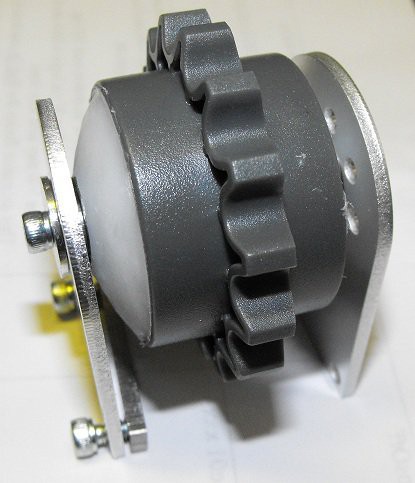
I think this is a good start to the free spinning sprocket but I still had to figure out how to allow the tread structures to rotate.
I originally planned to limit the tread structure rotation to a little over 180 degrees but I've decided the trade off required to get 360 degree rotation is worth the benefits such rotation brings.
The original 180 degree(ish) plan would allow the robot to stand on "tiptoes" and allow the robot to point the treads up. This tread up position was going to be the way the robot reduced the area it occupied. Here are some drawings of these various positions.
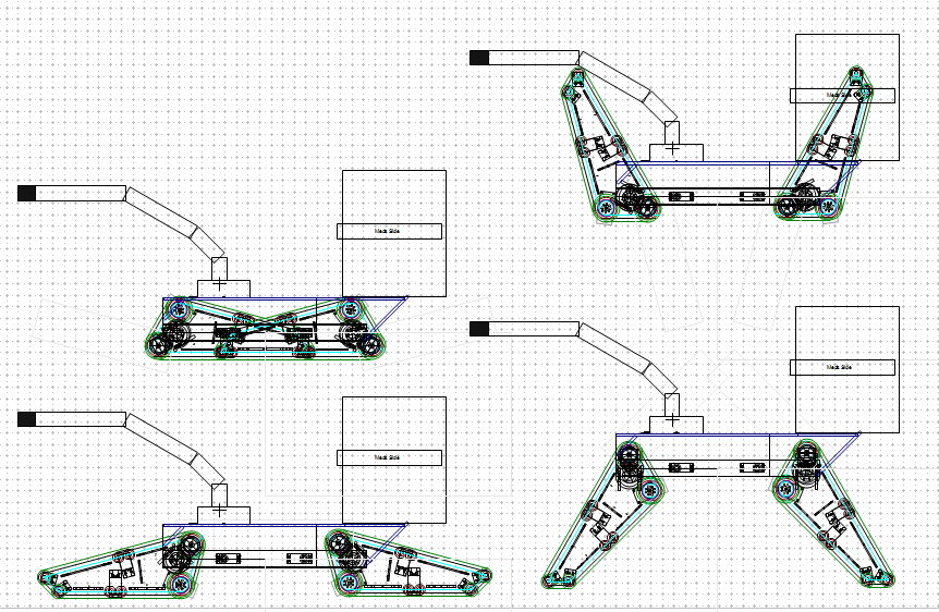
The configuration in the top left diagram wouldn't have been possible with my original plan. I think this top left configuration is so useful, it's worth the extra effort to implement.
In order for the treads to fold together like this, one set has to be outside and one inside. The drawing below shows how the treads need to be arranged.
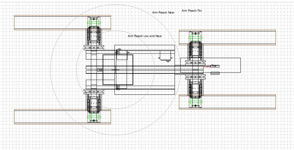
Since the tread structures can now rotate 360 degrees, the main chassis of the robot has to fit inside the narrowest set of treads.
My current plan is to use metal sprinkler pipe for the tread structure pivot axle. The metal pipe is 21.5mm (about 27/32") in diameter. Since the tread structures won't be moving either fast or frequently, I decided I could get by without bearings at the pivot points. I plan to use Teflon bushings.
I have some 1-1/4" Teflon rod which I've previously used as a bushing material.
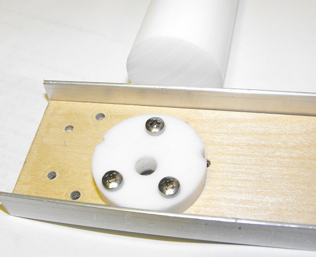
The above photo shows a Teflon bushing I used in another robot. The bushing for the pipe will have a much larger hole (21.5mm instead of 6mm). I'm hoping Teflon bushings will allow the tread structures to rotate freely.
I plan used a servo converted to a winch to raise and lower the treads. I knew I had previously purchased some big servos from HobbyKing. I was pleasantly surprised to find I had four of these servos on hand.
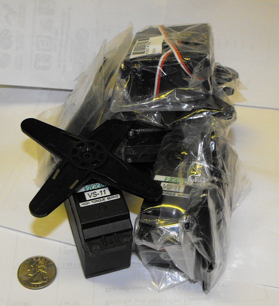
These are larger than normal servos and I'm hoping they're as strong as they are big. I'll likely convert them to continuous rotation and hope they and raise and lower the tread structures.
As suggested by the above diagrams, there will an arm on the robot. To illustrate the concept, I plan to use a CrustCrawler Smartarm.

I've had this arms for about 5 years but I haven't done much with it. I think it's a bit too heavy for this application but I think it will work well enough to illustrate the concept.
I'm hoping the arm can assist the patient with selecting the necessary items required for proper health maintenance.
While I haven't posted much about the project lately, I have been working on it since I found out I made the semifinalists. I'll try to keep you all updated a bit more regularly as I attempt to have something presentable by September 21.
Discussions
Become a Hackaday.io Member
Create an account to leave a comment. Already have an account? Log In.