 Eno423
The Malyan/Monoprice/<insert Chinese company name here> is a fine little & very capable 32 bit controller 3d printer with built in wifi.
I had the mini about 2 weeks before I started to modify it.
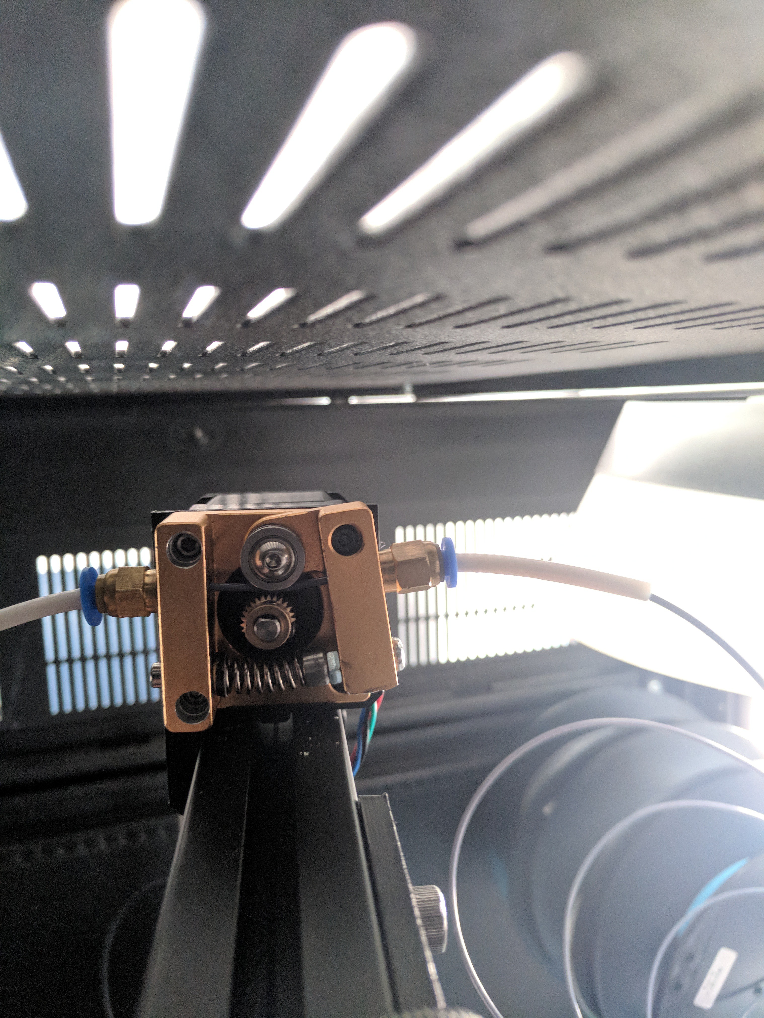
1 of the first things I HAD to do was replace the stock plastic extruder assembly.
However there were issues with it. the supplied screws did not fit at all in the holes, were to short, etc. So I threw it on my drill press & opened the holes a bit
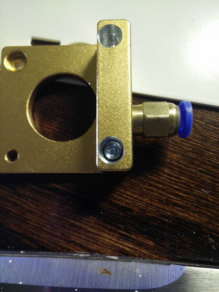
I after a little bit of time printing with the new extruder I began having some odd under-extrusion. I didnt notice, but the filament began cutting through the aluminium on the extruder housing as well as wearing/cutting into the frame
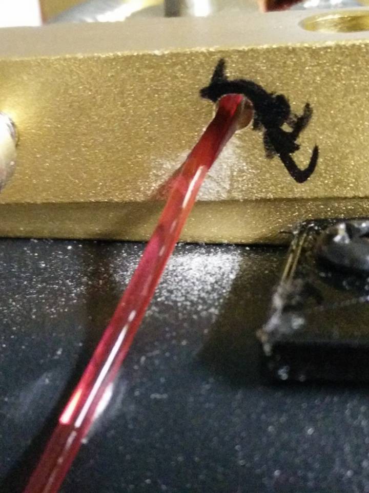
So i Drilled & tapped that end of the housing & placed another push fitting in & a small piece of PTFE. this worked much better, & is still setup like it today
The next thing to tackle was the Bed.. I went through & tried everything that people were doing at the time....glues stick, tape, hairspray...etc all junk. I then came across 1 of the first articles on PEI & decided to give it a try. At first I bought a small sheet from mcmaster carr, & some 3m adhesive & applied it directly to the minis Stock alum bed. However after some time, my printer started to develop the common bow in the build plate. So I then purchased a Borosilicate glass piece, had it cut & then installed a piece of PEI on it...It turned out to be one of the best moves I made. (however the first time I printer PETG & had good squish...it didn't come off so easily & had to buy a new piece of PEI as I screwed up the other piece
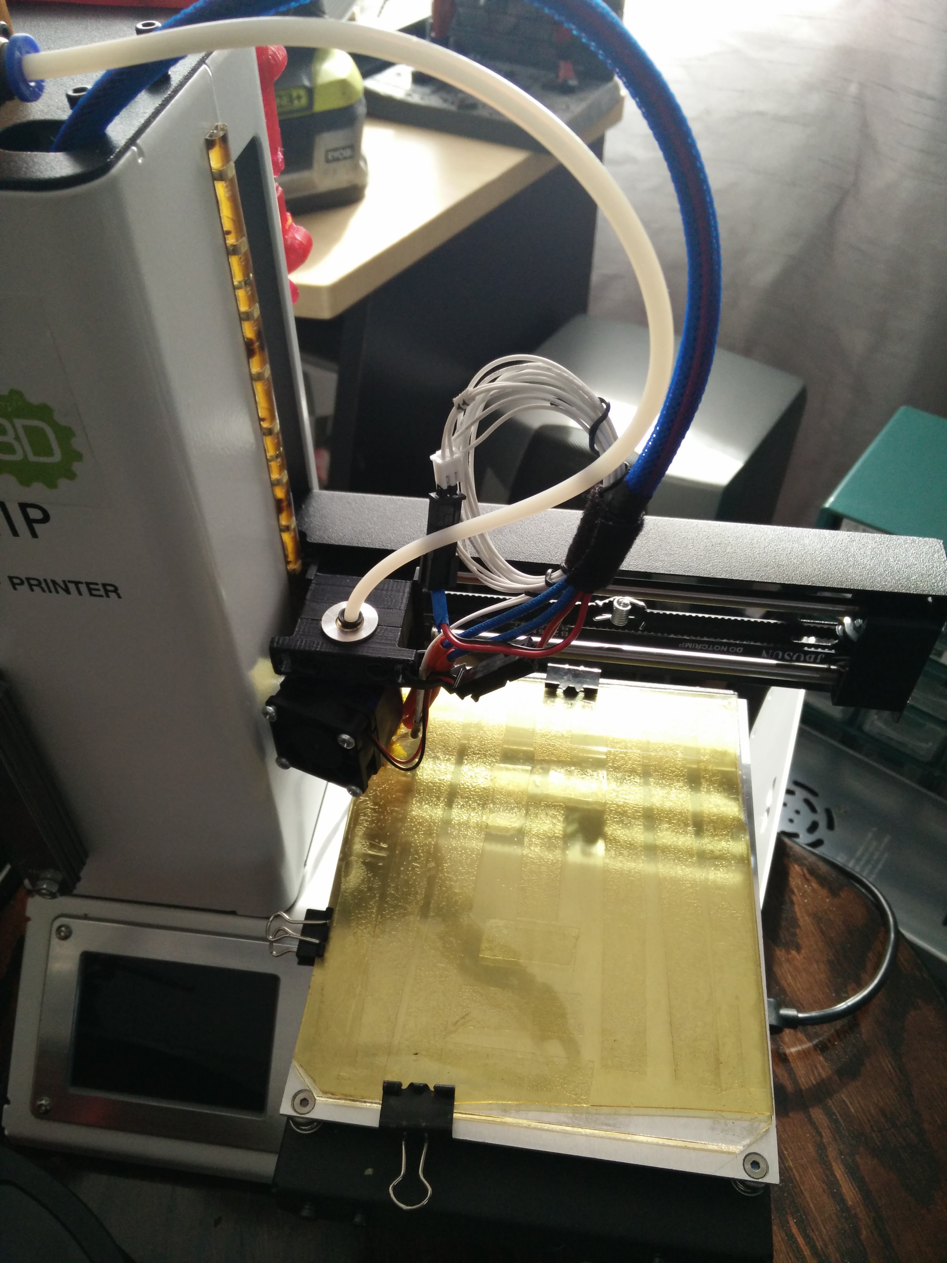
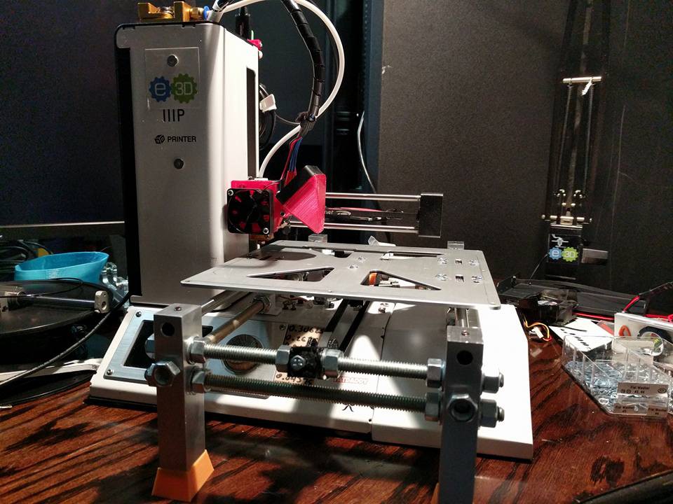
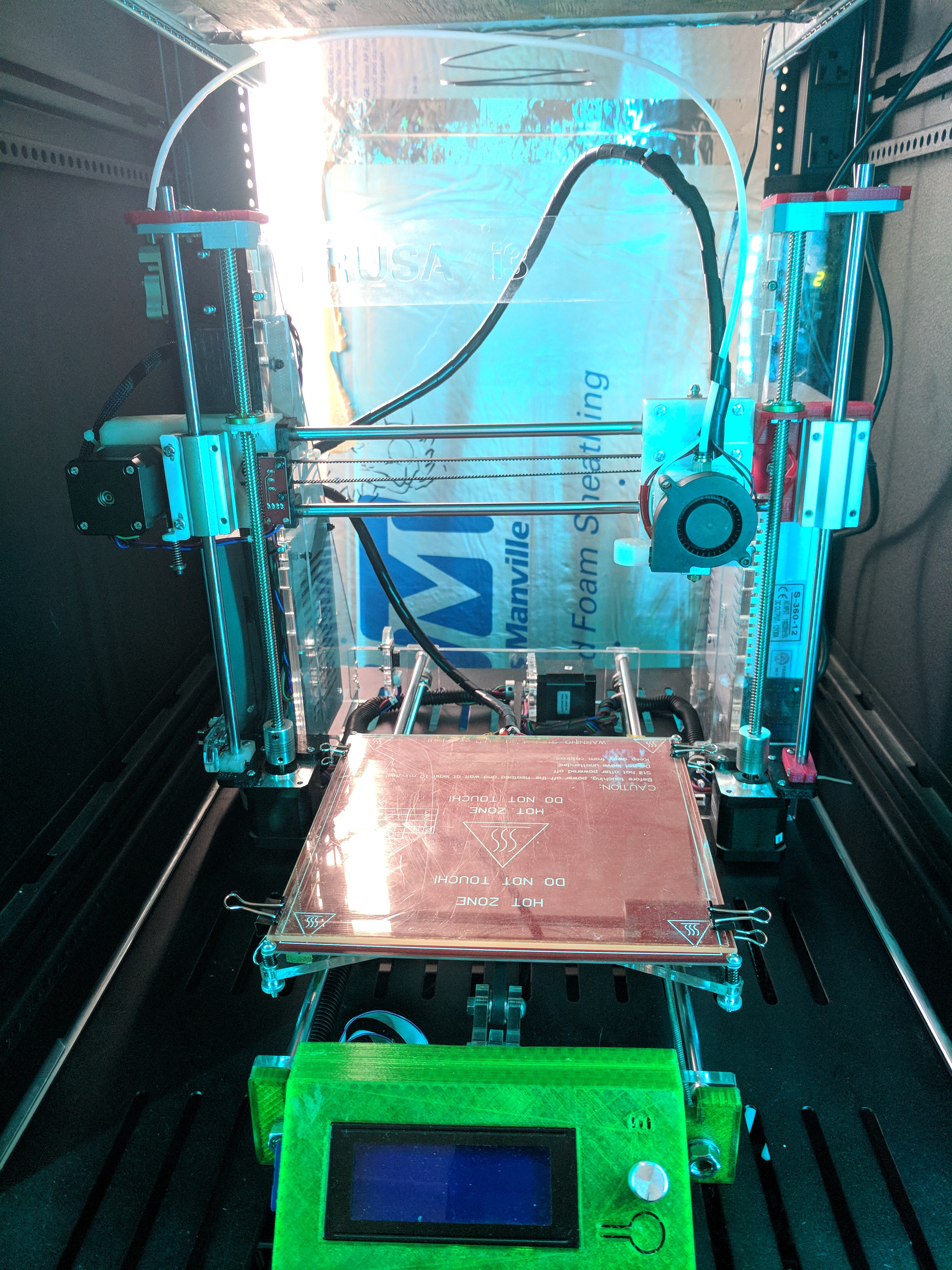
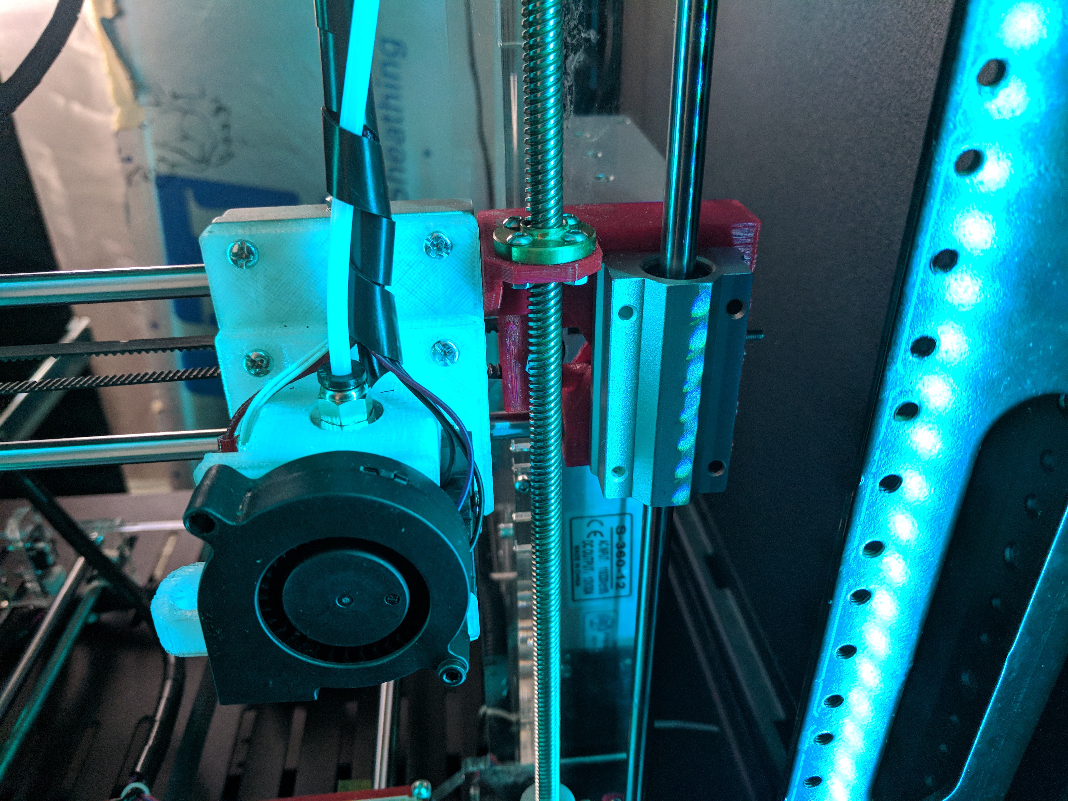
so as time went on I purchased more things...next up was a E3d v6 hotend
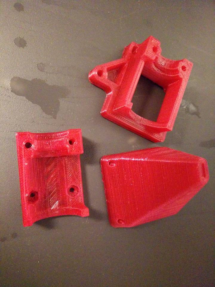
Which of course needed a new mount setup. I went through so many different version to finally find someone who had a close sit to what I wanted. I modified their files & printer this out in some PETG
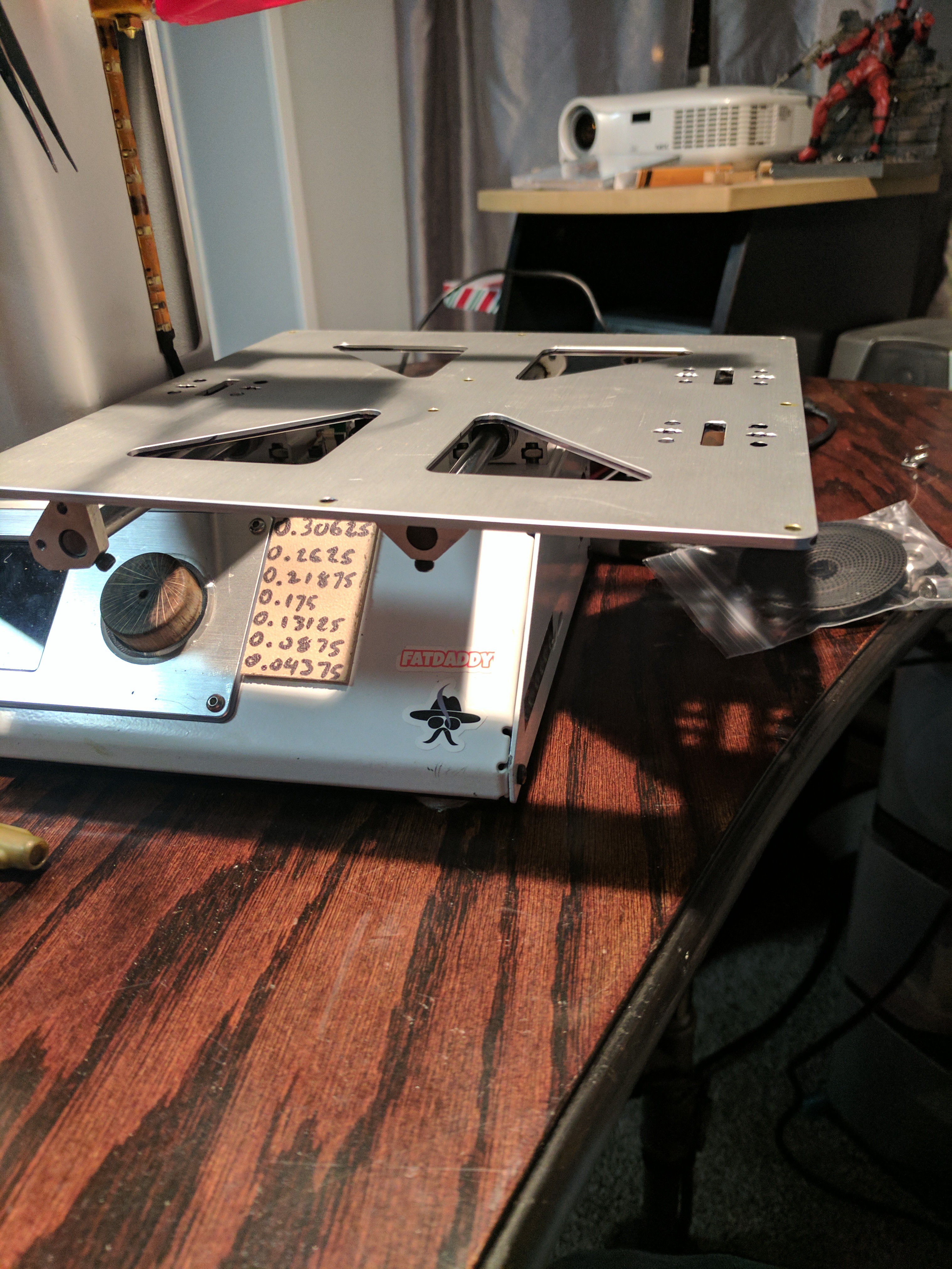
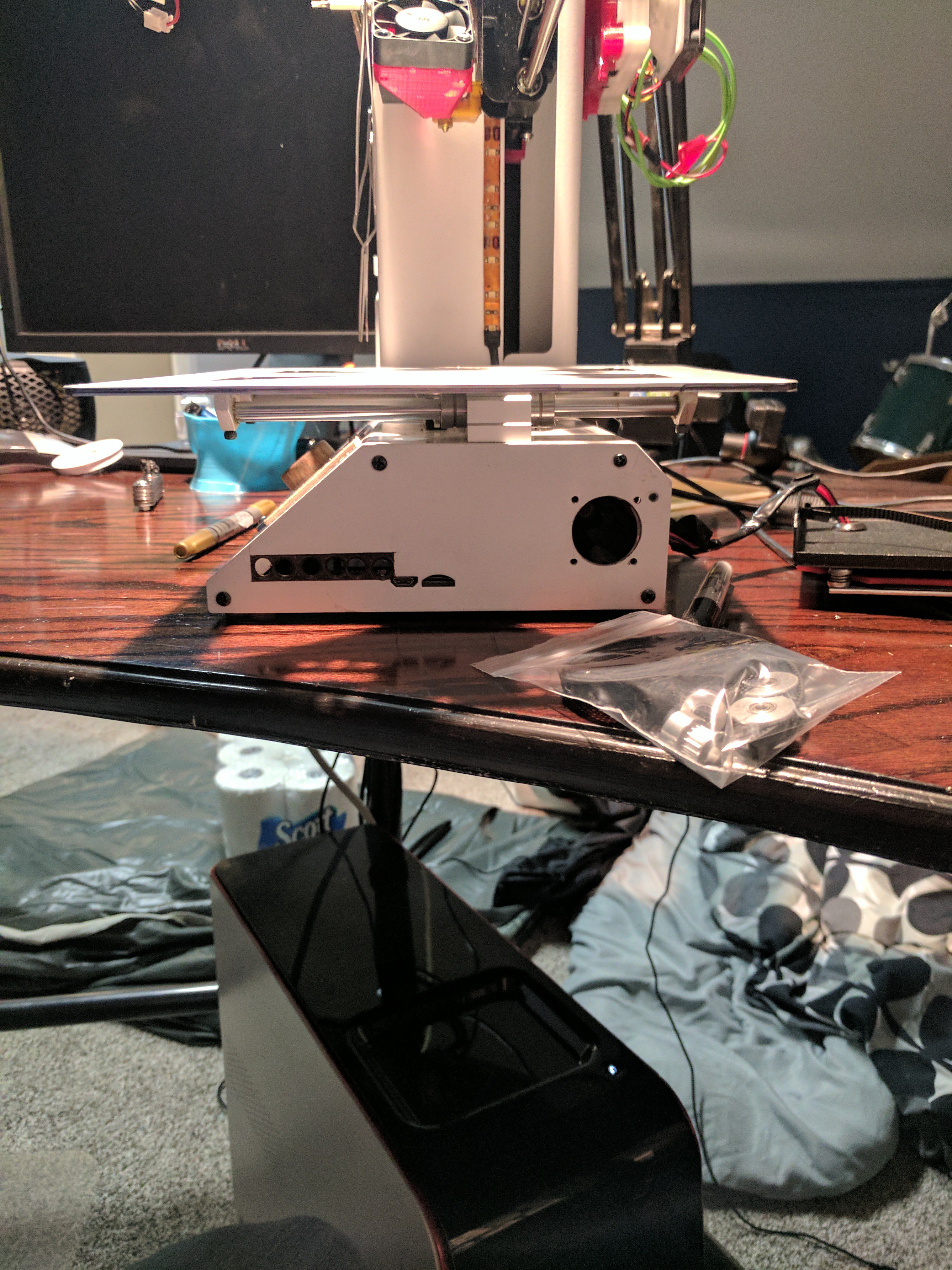
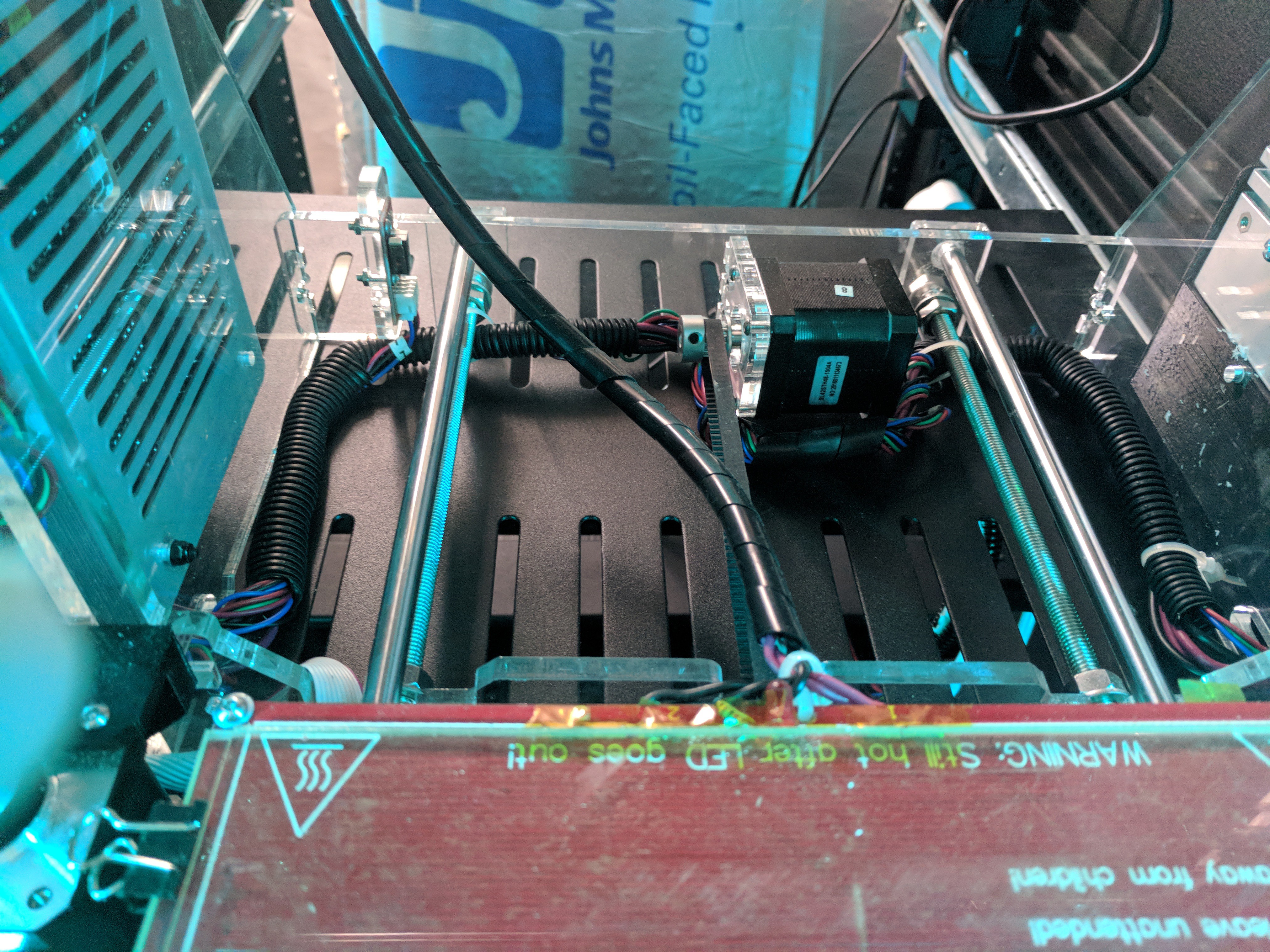
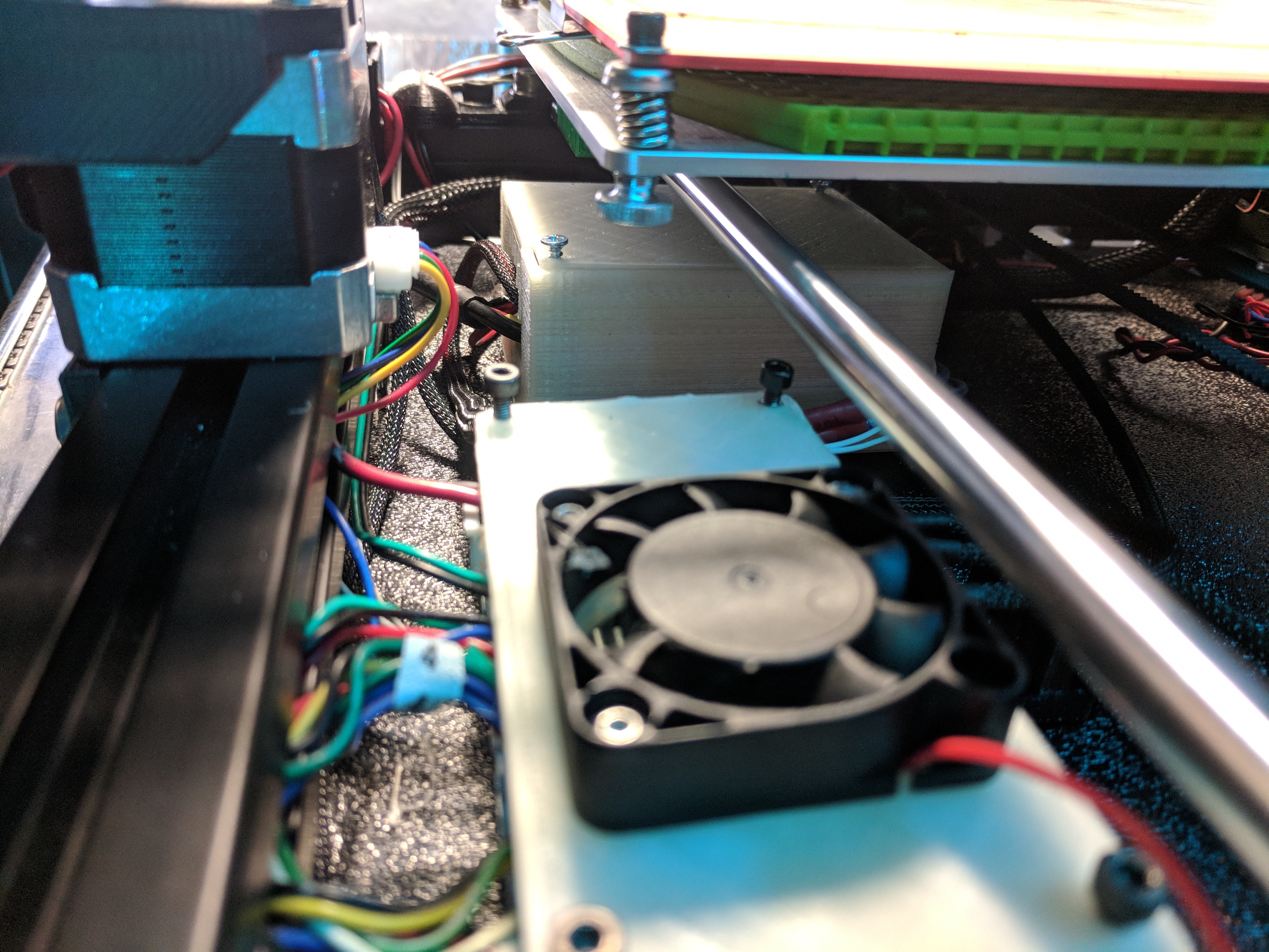
As I started doing larger prints, I noticed I would have weird issues. Thanks to the FB group & community, we were able to determine that there was little/no airflow to actually cool the heat sync on the steppers & when it started heating up, LCD would have issues, printer would under extrude, etc.. So a few fans (1 at each opposing end) wen in the frame bottom, & some holes cut in the one side panel to allow the air to escape
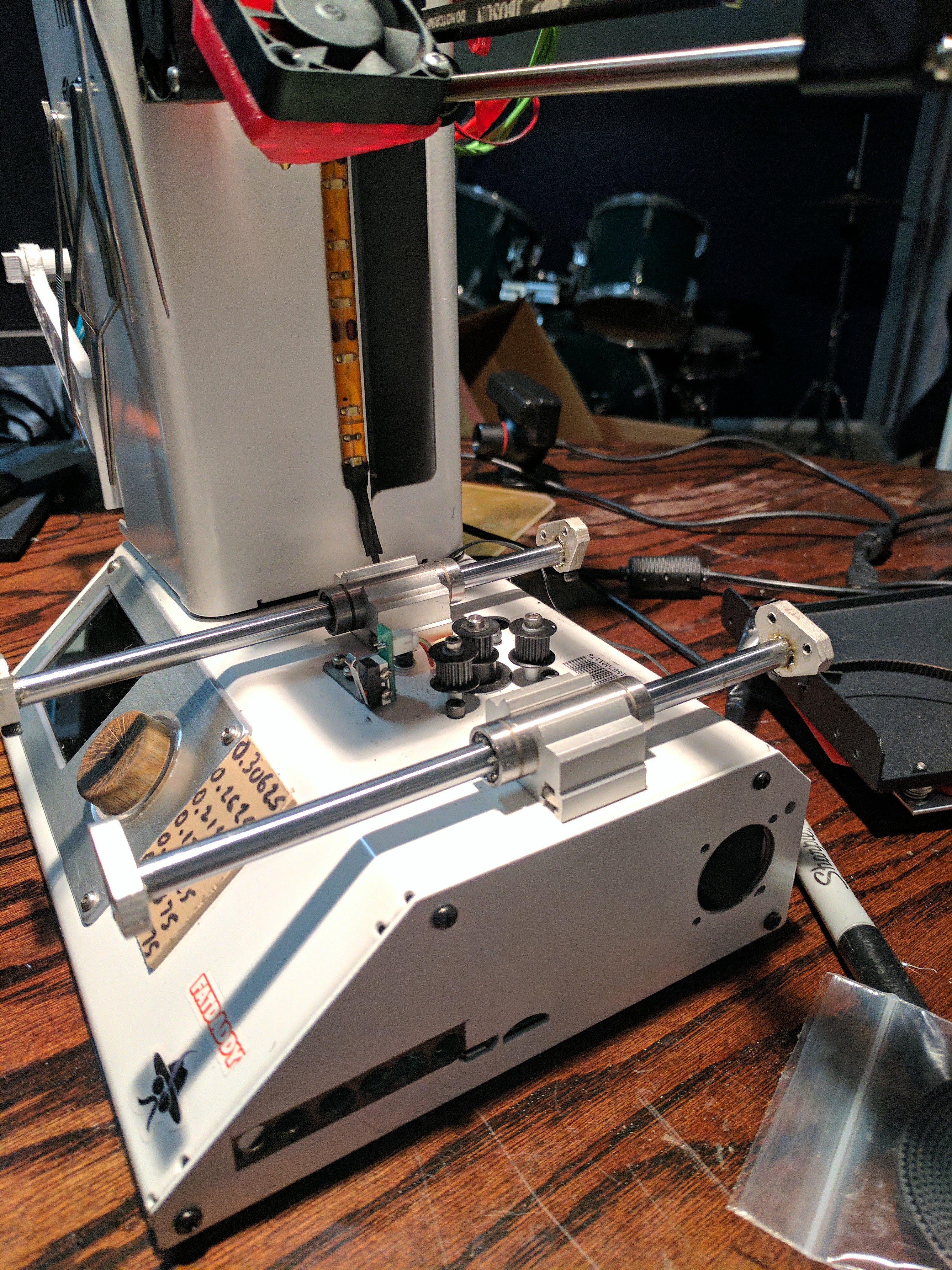
During this tear down/rebuild, all plastic pulleys were replaced with metal & GT2 belts, A LED strip that was wired into the 12v of the power-supply was added as well to light up the bed better.
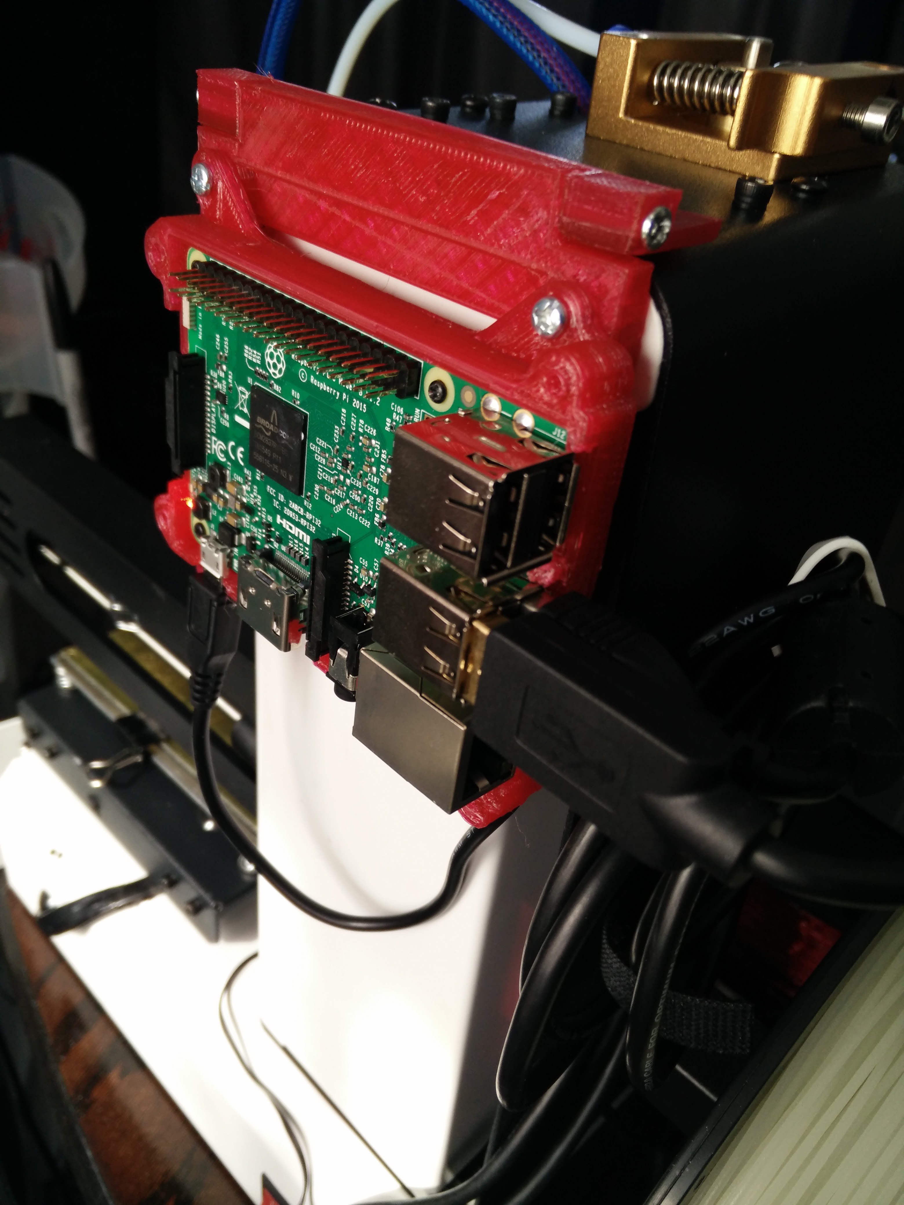
I took my Raspberry pi, printer a case & started using Octoprint
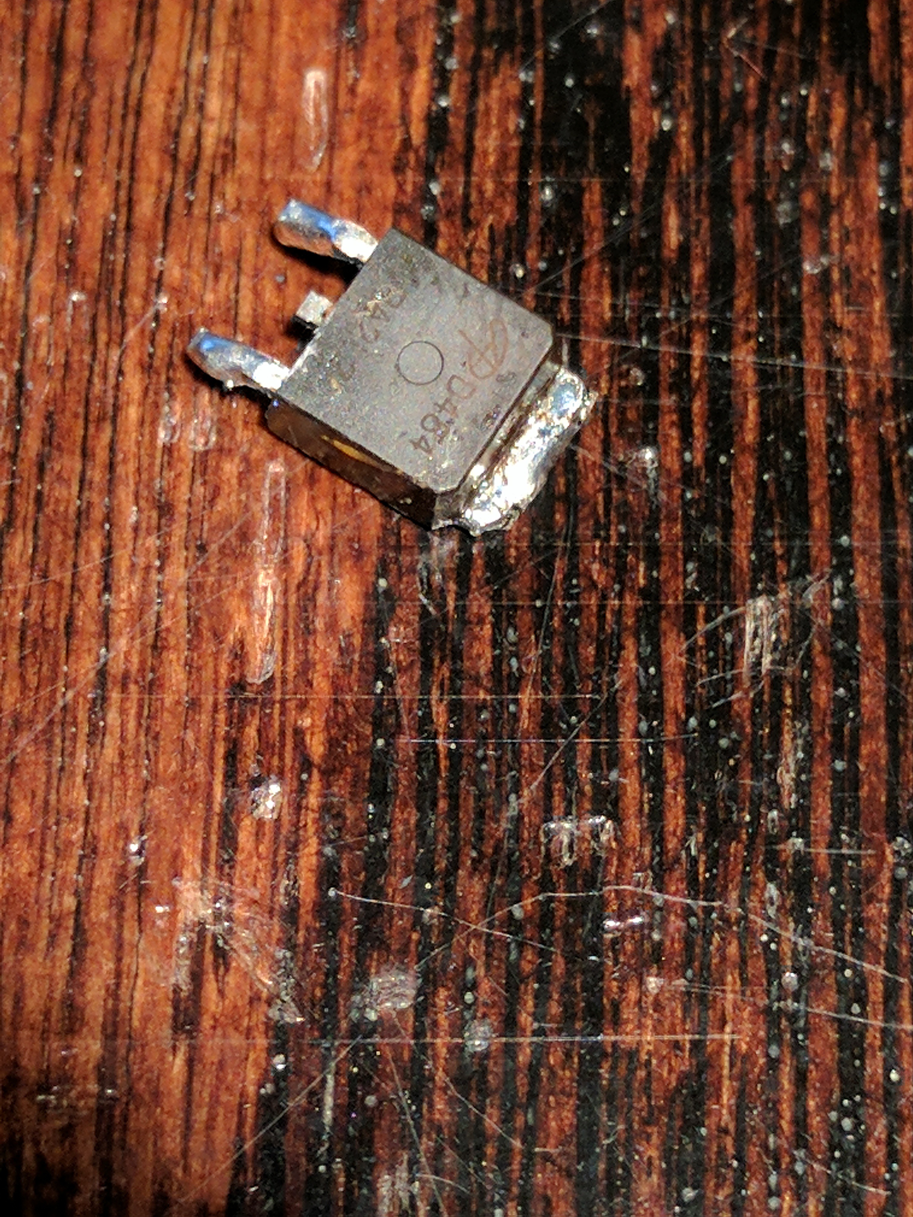
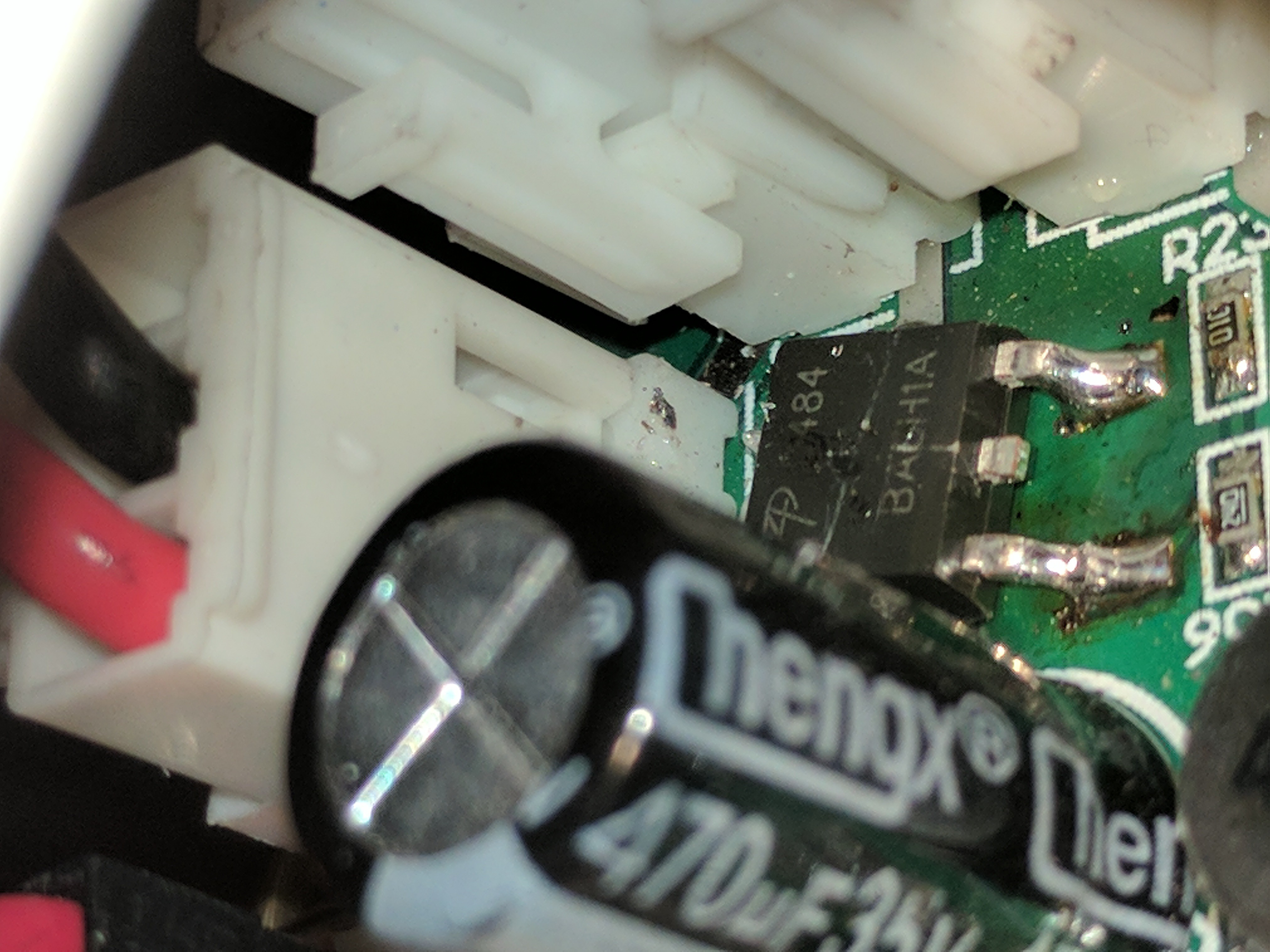
At some point in my modding, my ham fist knocked a binder clip onto the damn controller, thus shorting out 1 of the FETs on the board. I had to de-solder it (which if you don't have the proper tools & have large fingers like mine,,,getting to this cleanly was a pain. I managed to remove part of the trace, however there was still enough left for me to solder the new fet, though I had to do it crooked due to space, & where the pad was still left....also I don't have ANY surface mount/hot-air re-flow stuff, & just used my (at the time) only Radio shack Super large very unbalanced soldering iron
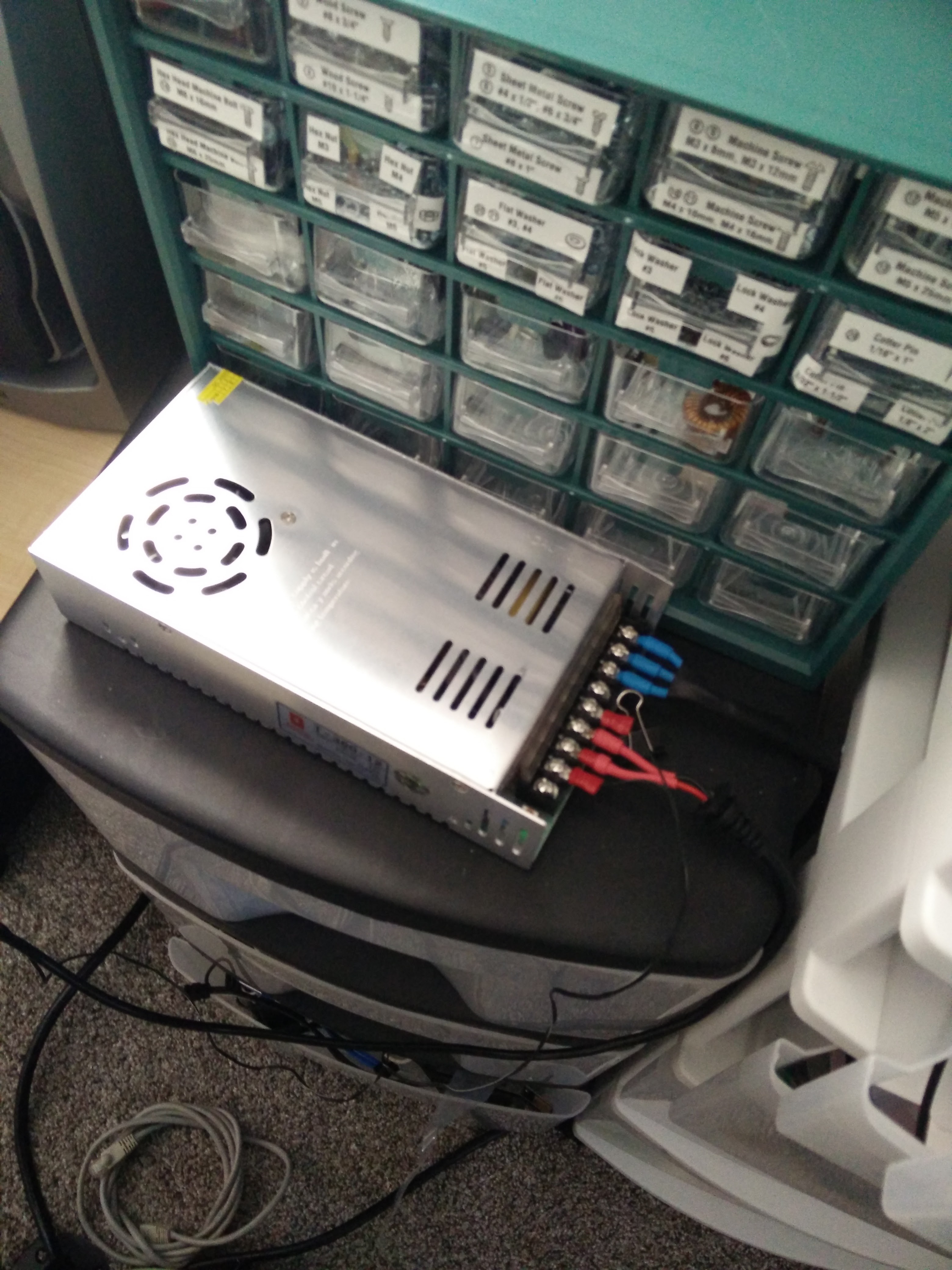
Around this time, I started getting the itch to expand the bed a bit...first thing I did to prep was purchase a better power-supply, as the brick it came with started having issues as well
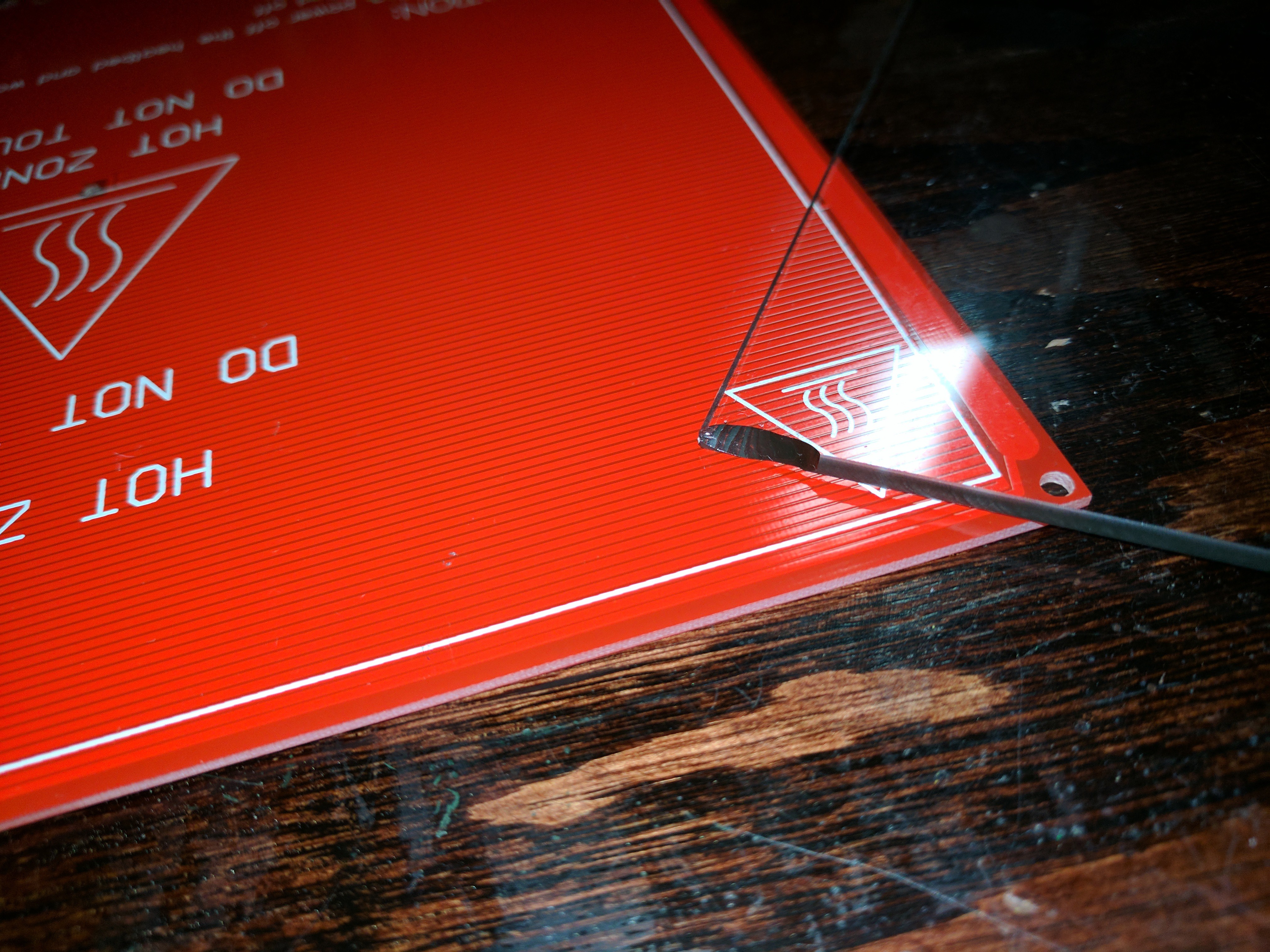
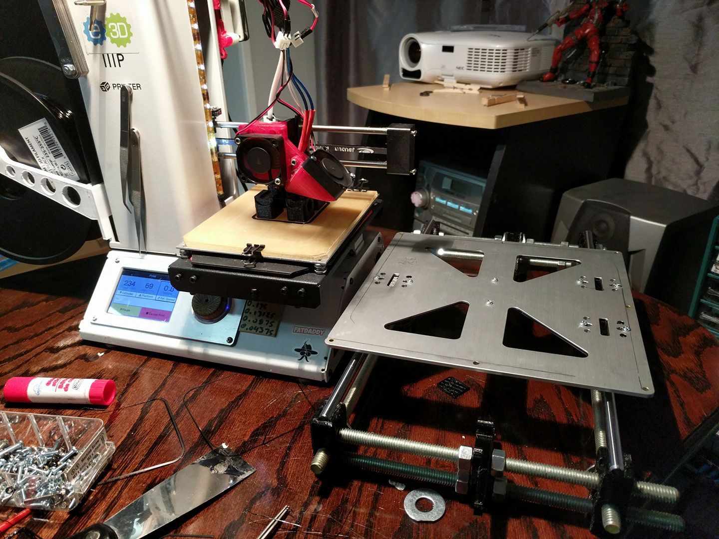
I purchased a Rep-rap champion Bed carriage & a 200x200 PCB heater
the first bed I got was severely warped & when laid flat on the table was about 1/4-1/2 high in the middle vs the ends & the new piece of boro I ordered was cracked in half. After emailing rep-rap champion, they were AWESOME & sent me a new bed & piece of glass, though this piece did come with a slight chip, I didn't care this time
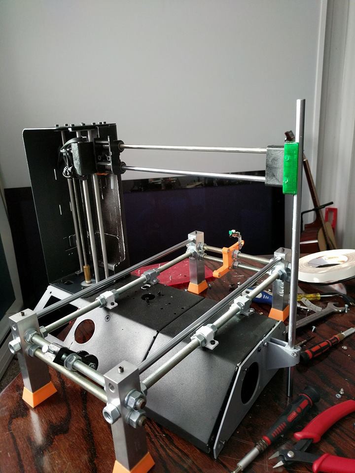
I then ordered my rails, bearings & began working on my design for the bed mounting since the stock setup wouldn't work
after much much head scratching I decided to build a standard i3 frame for the bed & then "Mount it somehow"
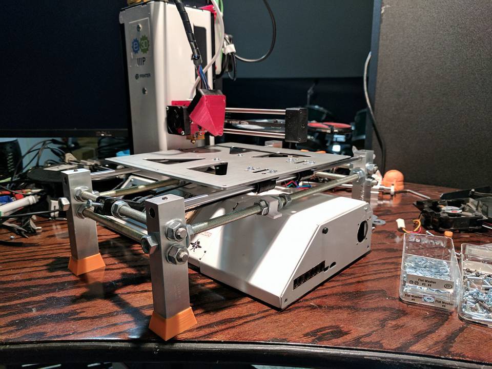
Initially I printed the end pieces for the bed frame, & assembled everything, only to then realize at the last moment, that the legs were too small to reach from the minis platform to the surface the printer was sitting on.
So I drew up some legs going off my dimensions, & gave them to a guy I work with who has a mill & had him mill me these..
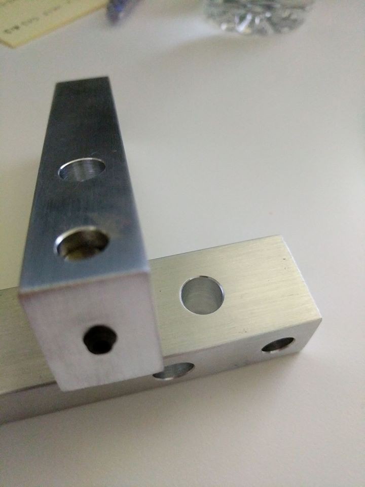
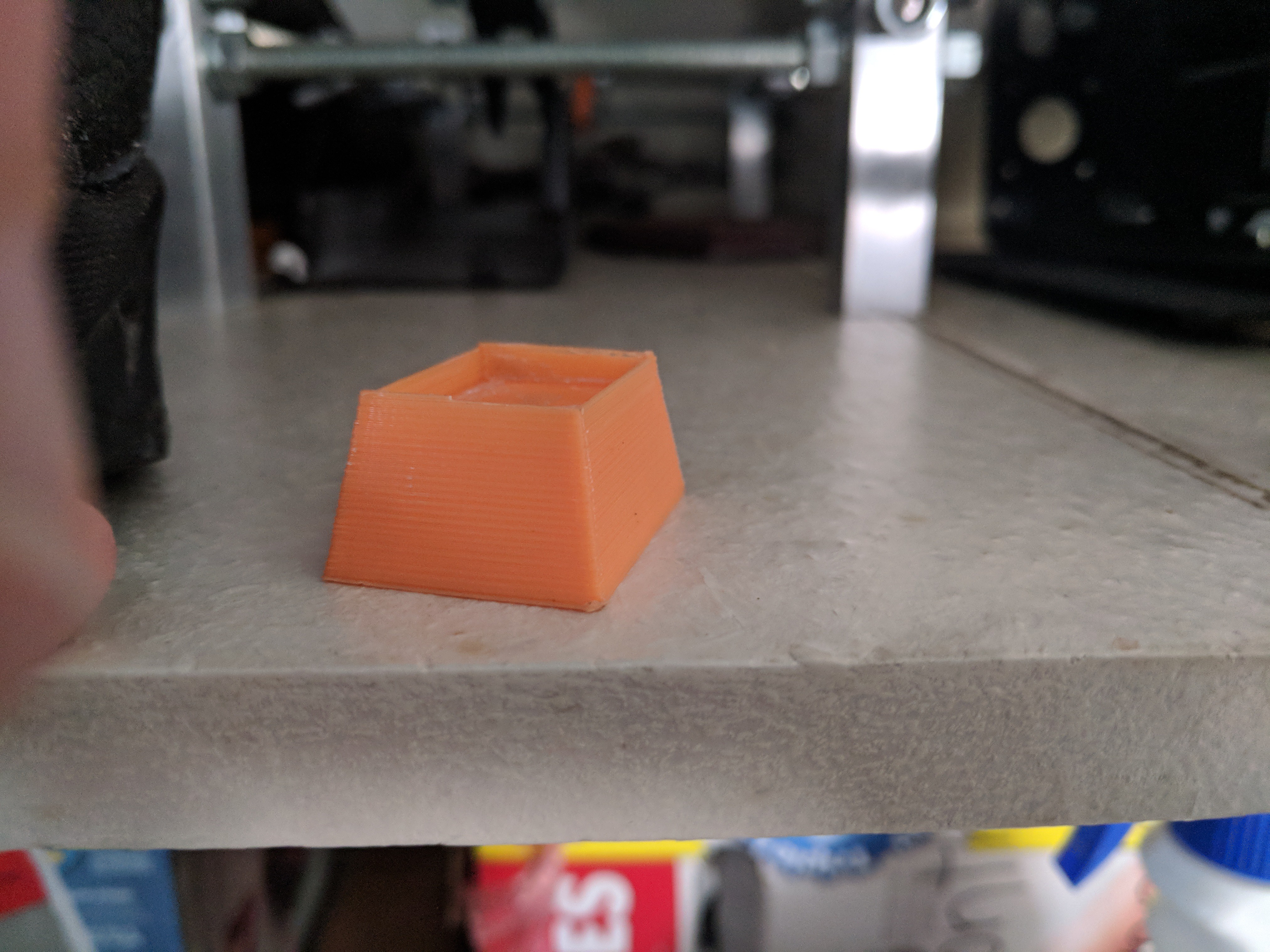
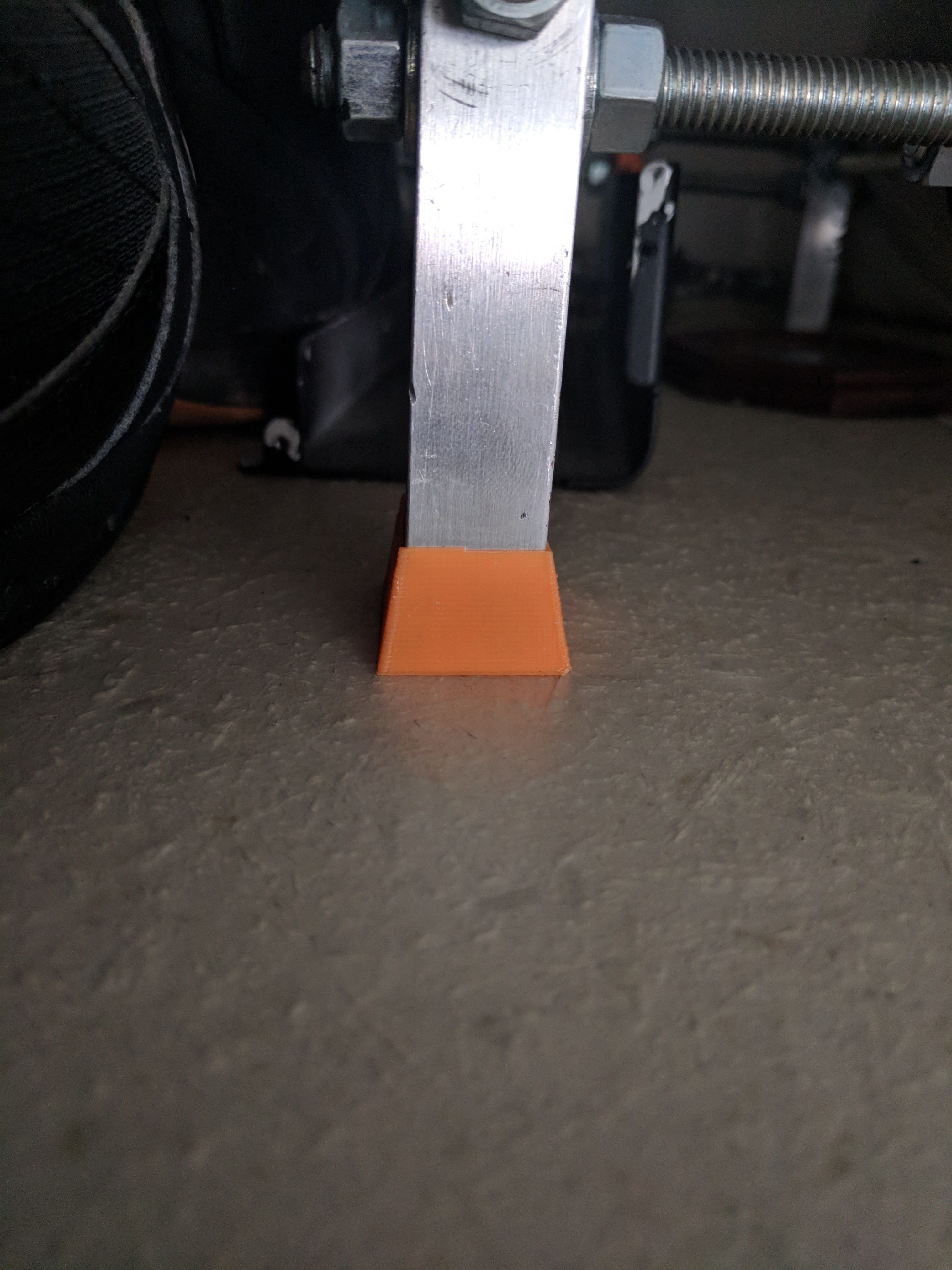
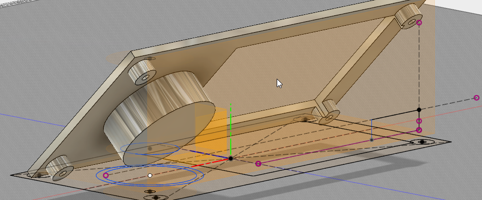
Its always good to have your printer sitting in the state it will live its life. For me, when I measured the height I need the legs to be, I didn't have the bottom on the printer & I didn't account for the feet on the bottom of it so my measurement was a bit off & the legs to short...No prob,,,I have a 3d printer, & designed some feet for the legs in Fusion
Now that the bed frame was good to go I needed to fab up a way to keep the bed frame sturdy with the main frame.
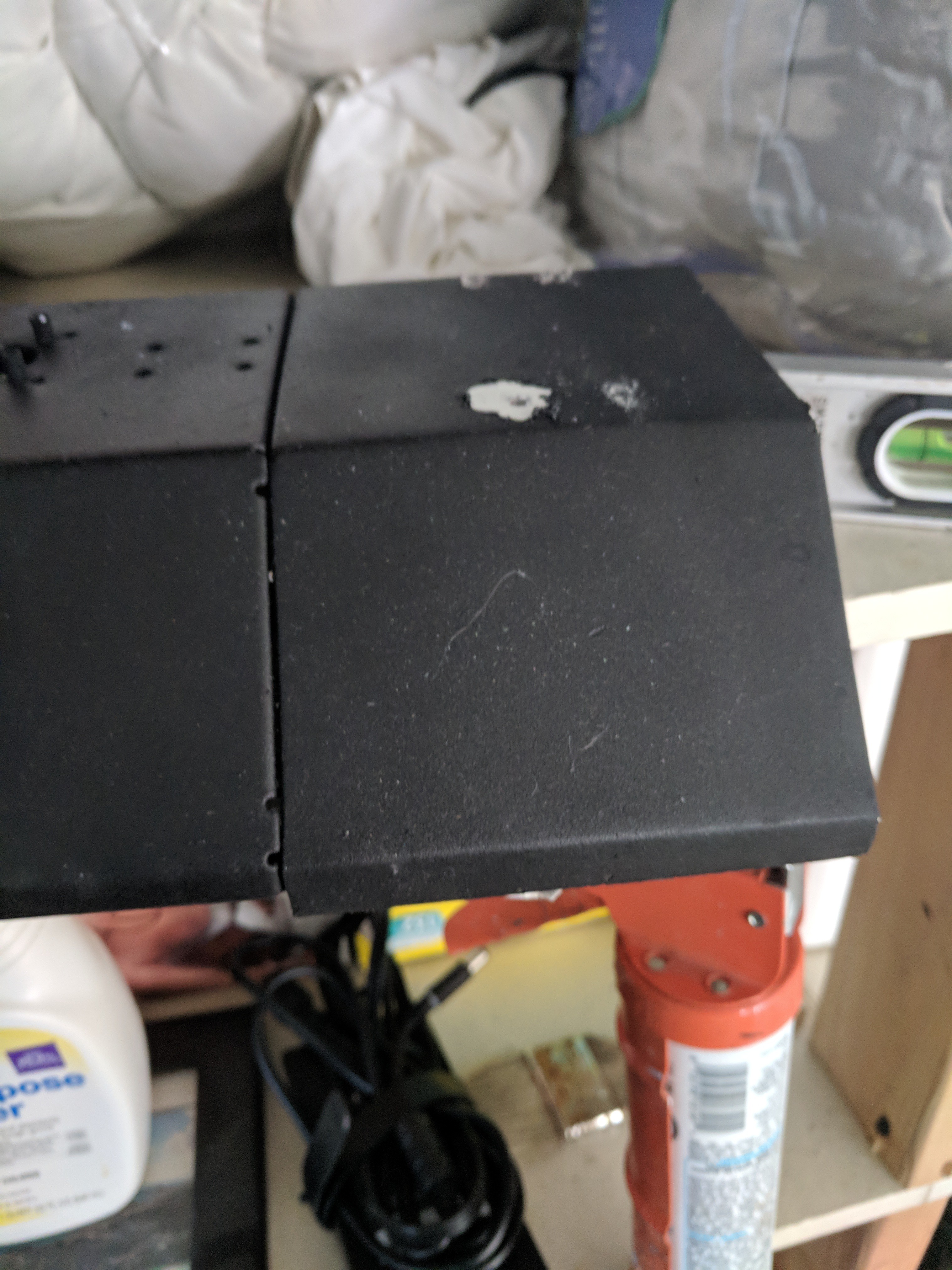
I took some steel I had laying around from a body panel job I did on my car, bent up a piece at the same angles as the minis main frame. Since this was a scrap piece of metal, it wasn't a perfect piece. the only spot on it large enough to work had a chunk cut out of it, so I had to do a lap (underside) & butt weld on the face to join the far right/bottom side of the extension. I also welded tabs/mounts on the sides of the extension to allow me to bolt it to the side of the mini & bolt the minis stock side panel to it. (pics are recent for this post, as I cant seem to find the older pics
bottom / inside of extension frame
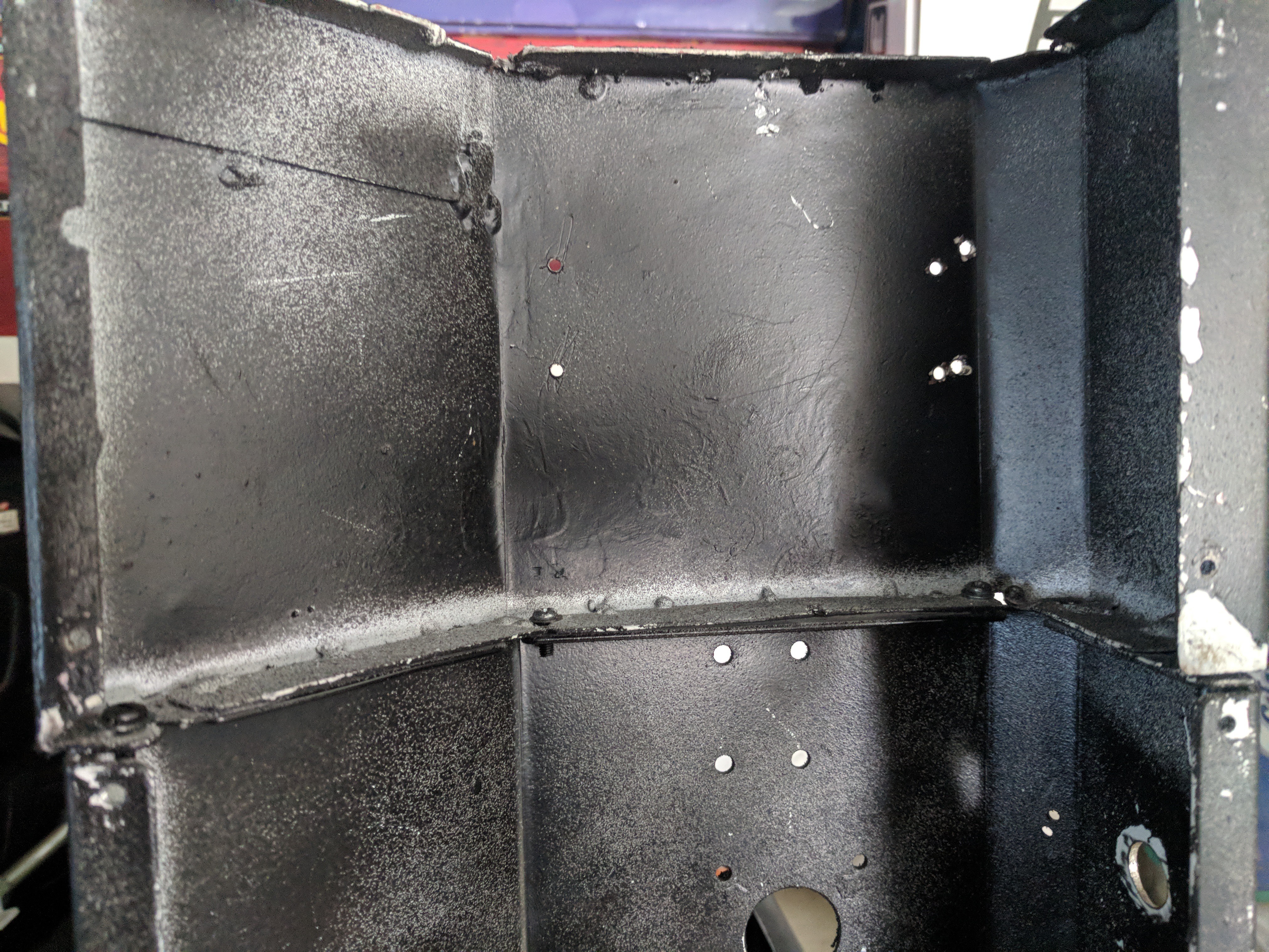
Back side of extension (holes are for mounts that held the threaded rod of the frame to this extension)
Front of extension
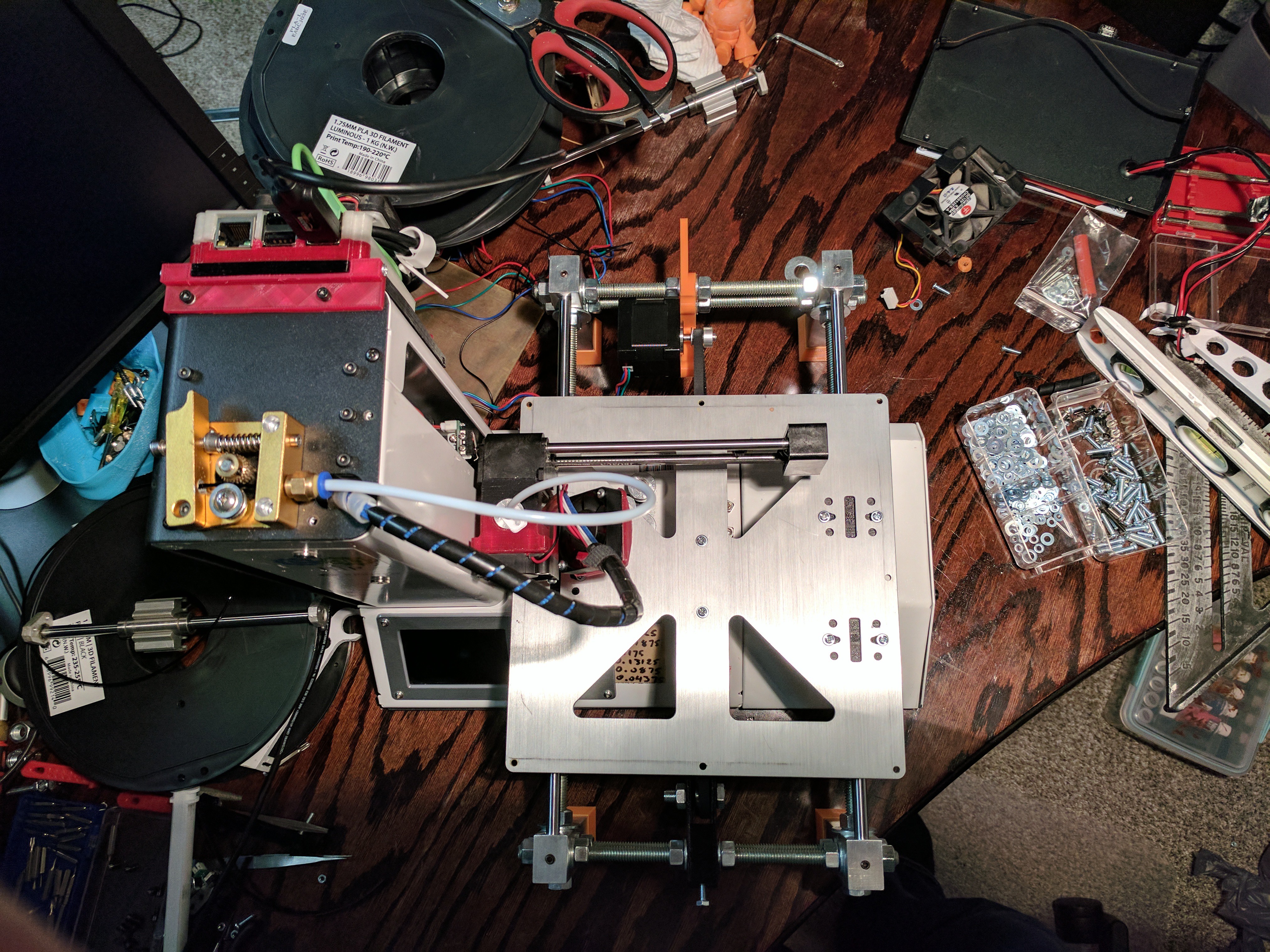
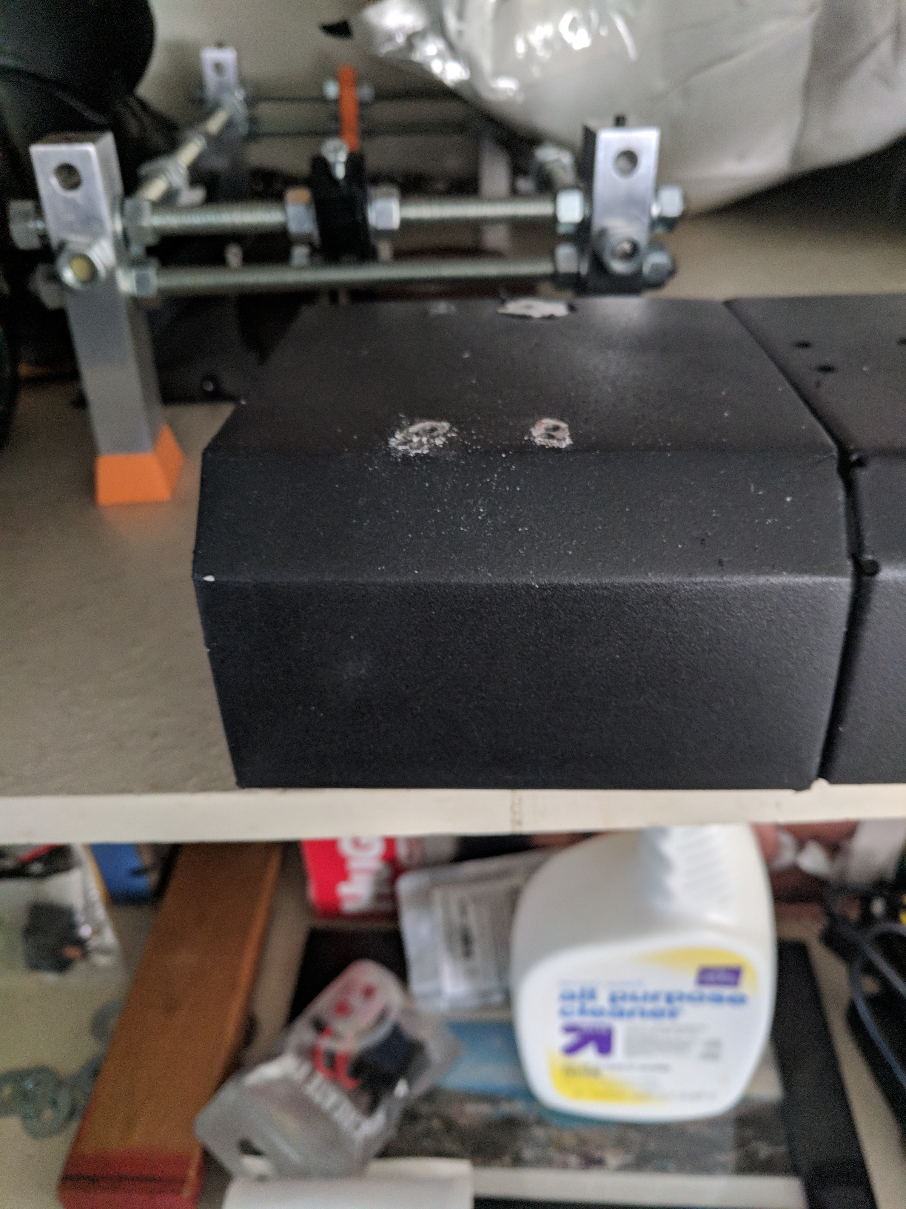
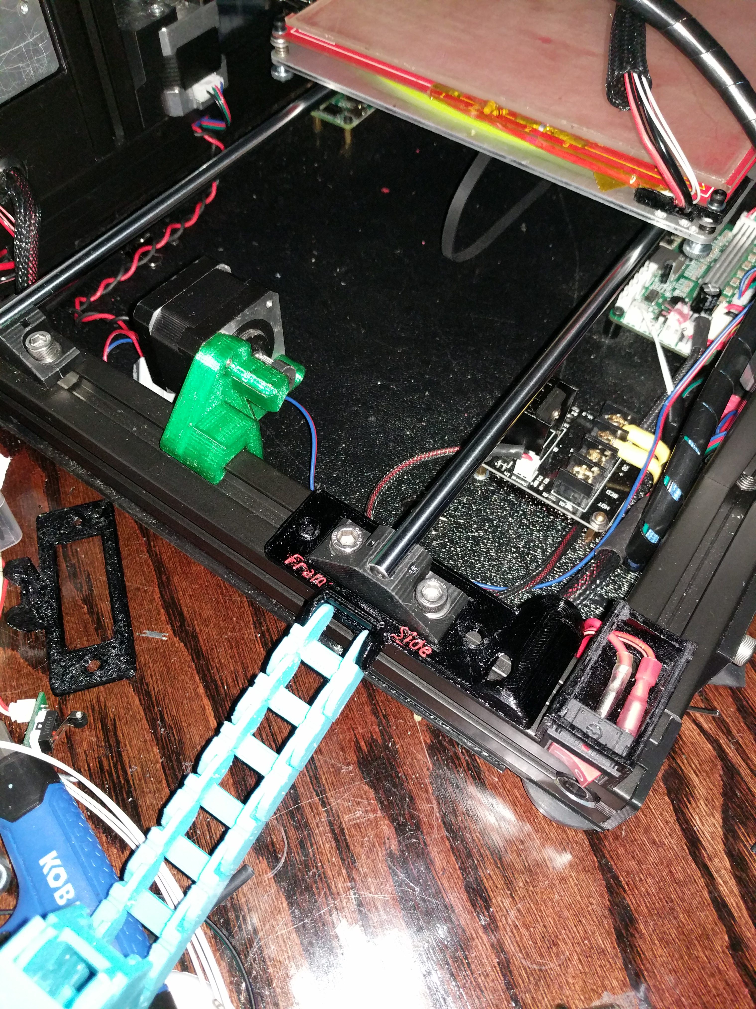
As mentioned above, I had to attach the y bed frame to the extension/printer frame. In this pic you can see a little white block in-between 2 nuts on the threaded rod. each side had 2 of these (1 front 1 back) to join the bed frame to the extension/main frame
Now with the hardware mostly situated, I turned my attention to the electronics.
(need to find pics)
With the new power-supply, I purchased a mosfet, a few power dis blocks for LED's/fans.
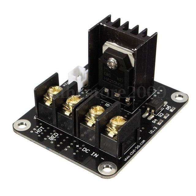
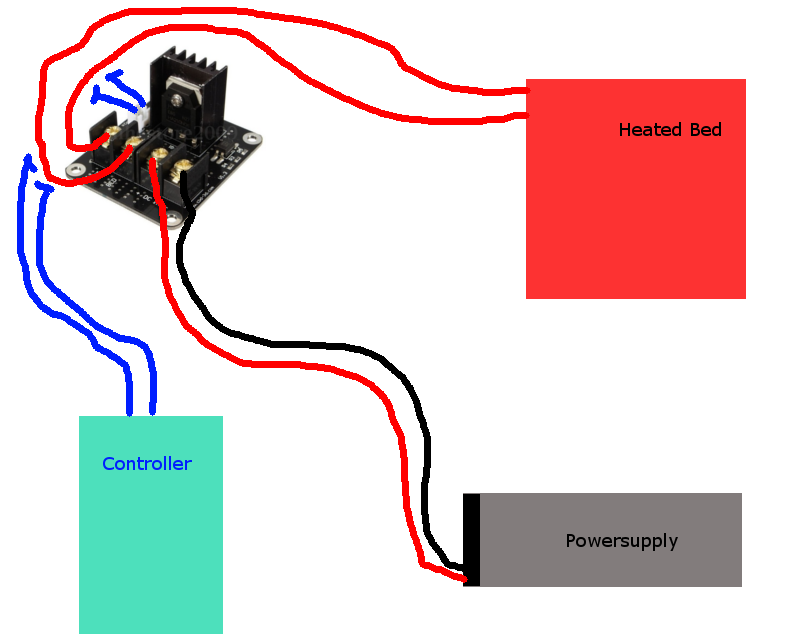
the new wiring for the bed goes:
wires from the bed heater go directly to the mosfet, the mosfet connects to the original controller board. This way when the bed needs to heat up, it pulls its power directly from the power-supply instead of the controller. This allowed me to have more stable & fast/more consistent heat ups on the bed
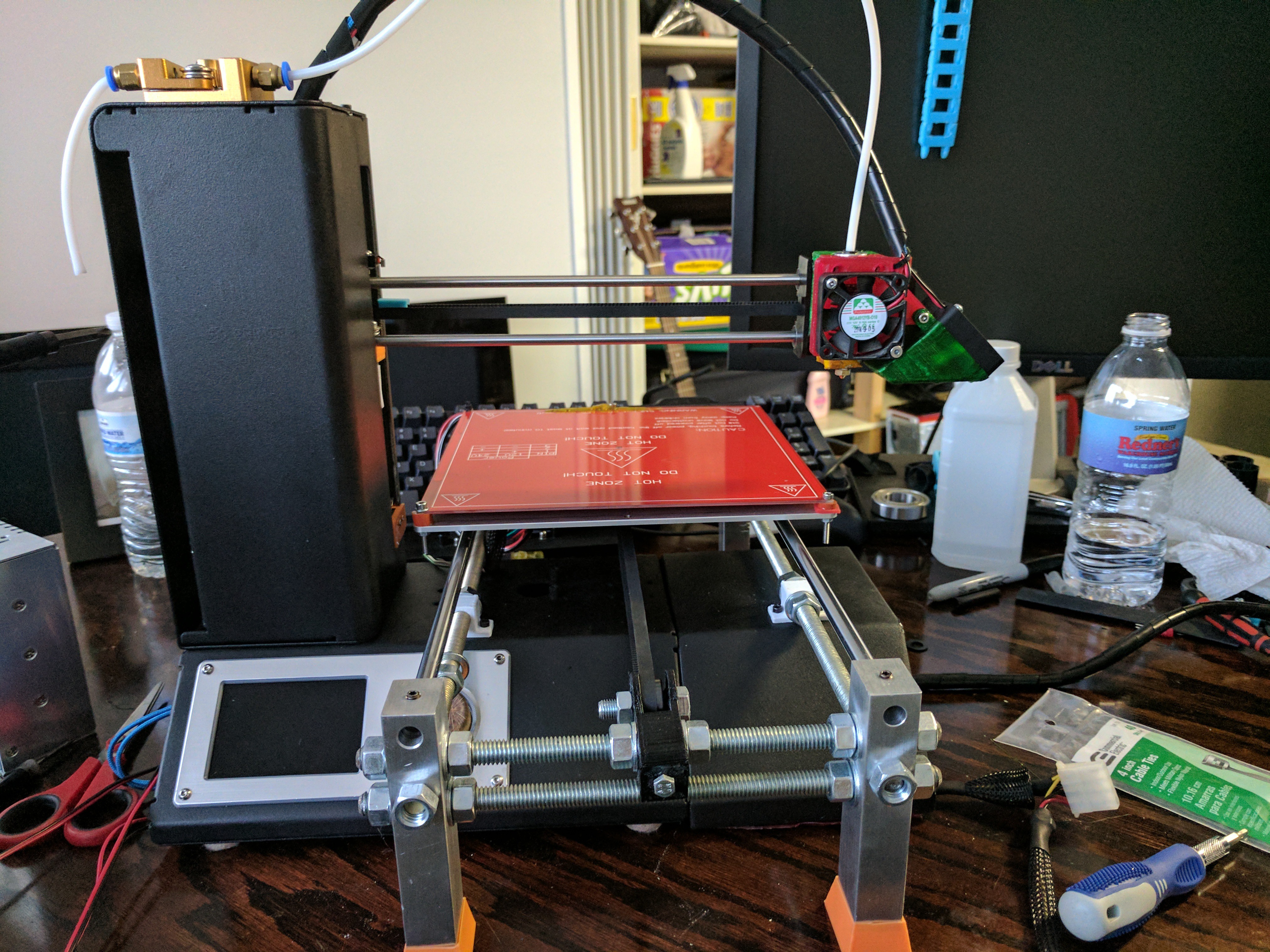
Now that I had a larger Y axis, I ran a test print./ (those that play CS Go probably know what it is)
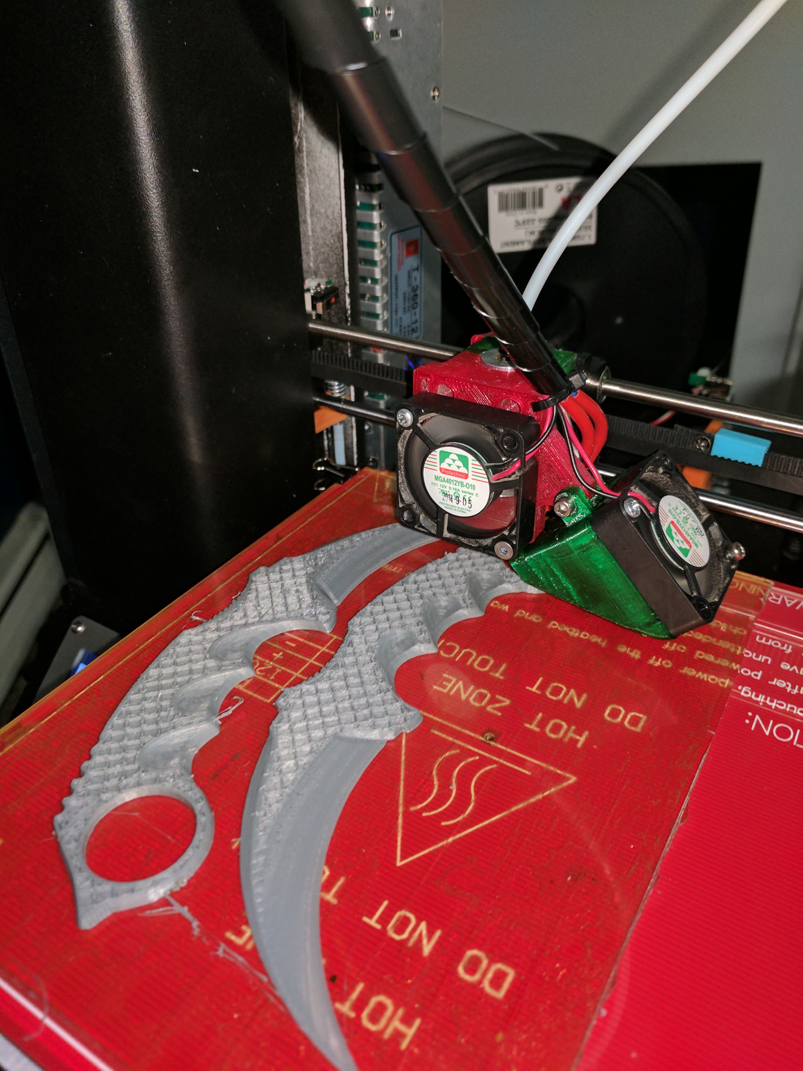
So far so good.
Next I turned my attention to expanding the X axis so I could use the whole bed.
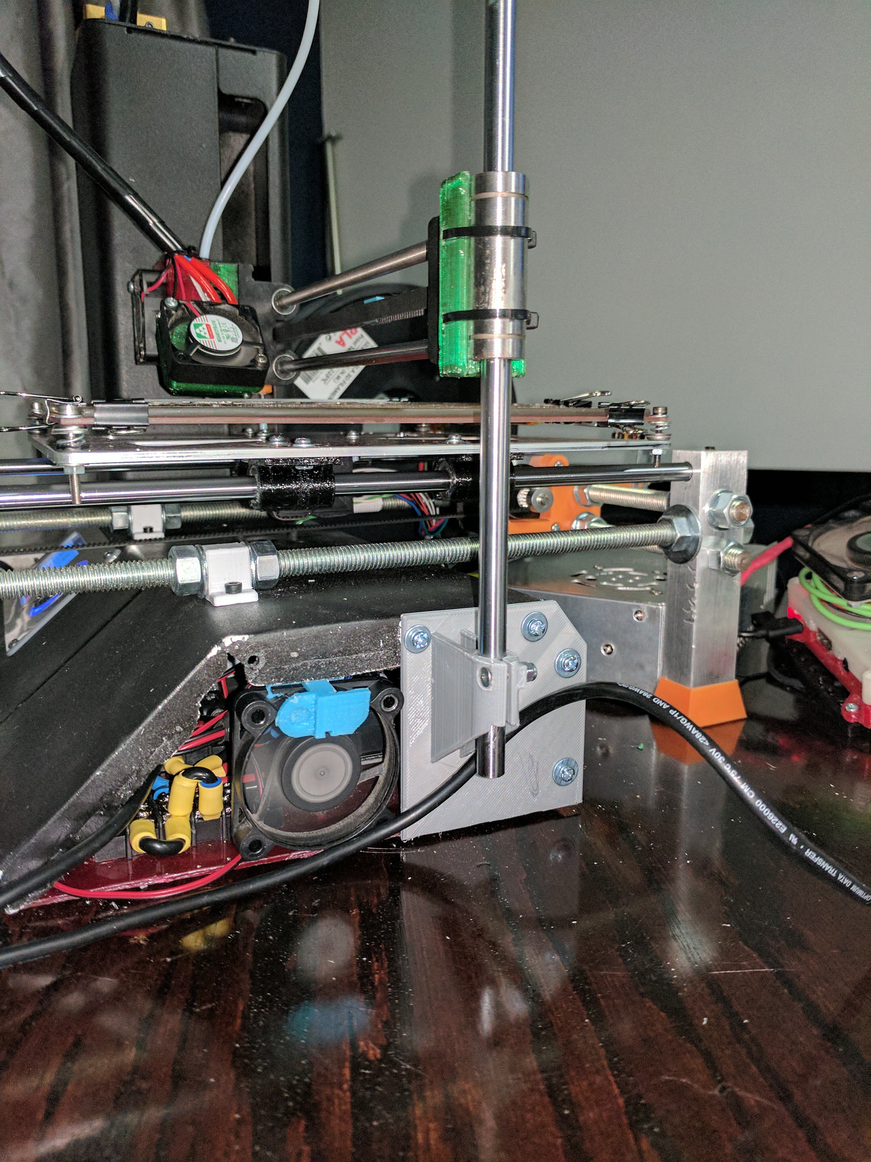
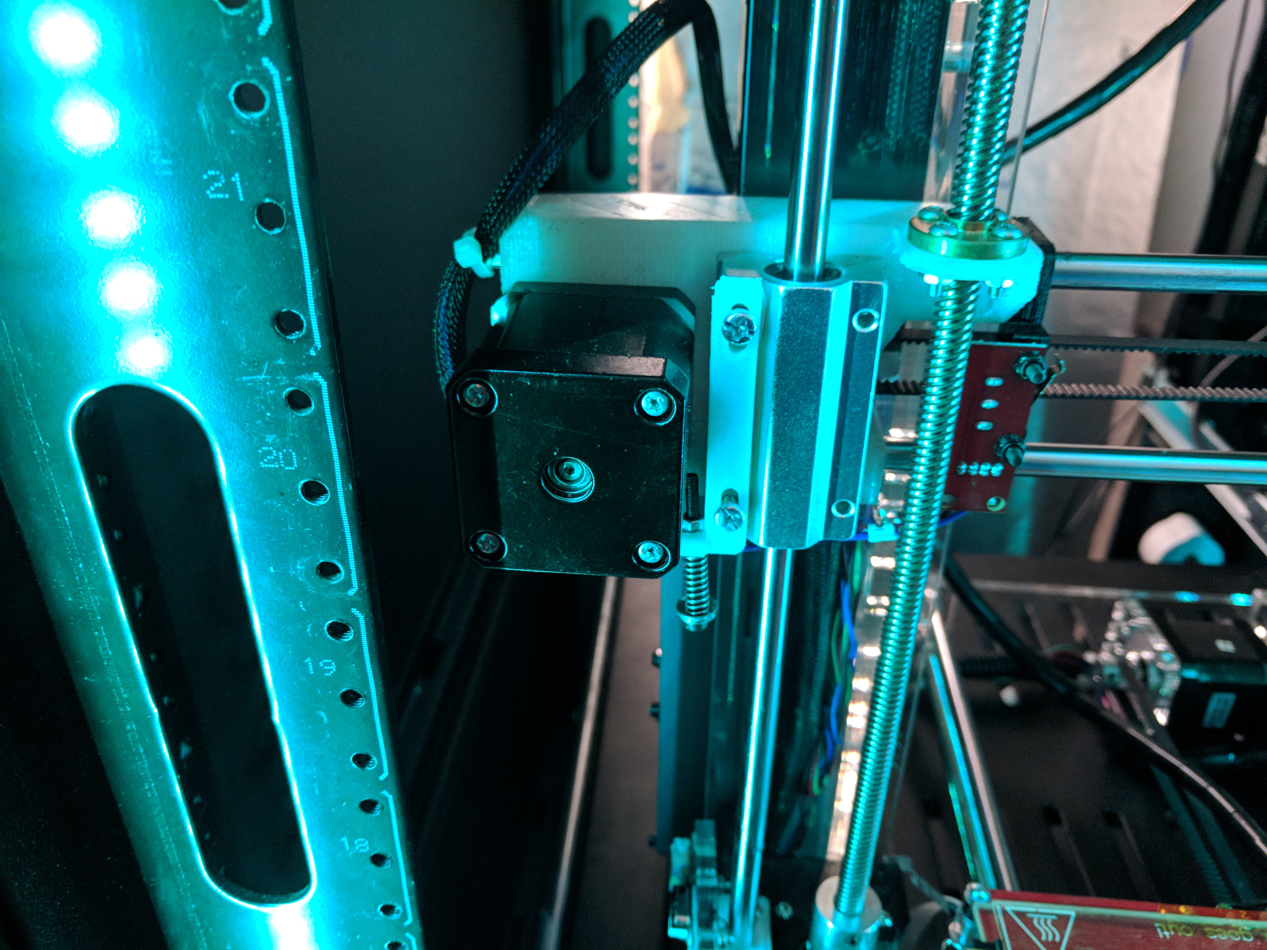
I ordered some smooth rods, cut them to length, then started messing with a way to support the end of the X as it drooped a bit near the end. Decided on going with a mount to mount a long bearing, & then a vertical piece of smooth rod for the end of the gantry to ride on. (this does/did have some issue, but compared to allowing the arm to just freely float, this was better)
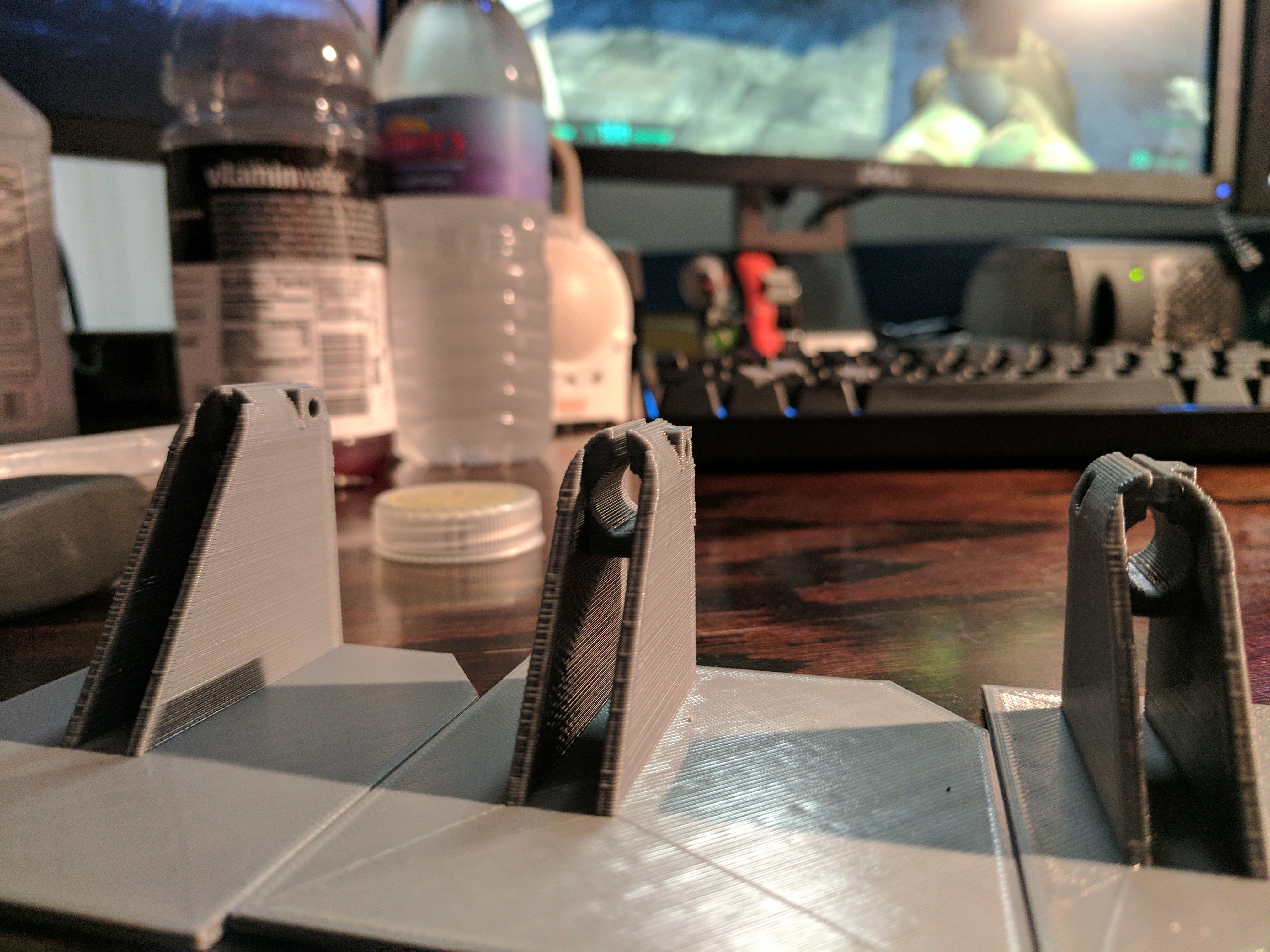
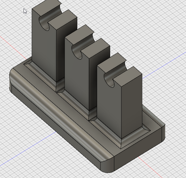
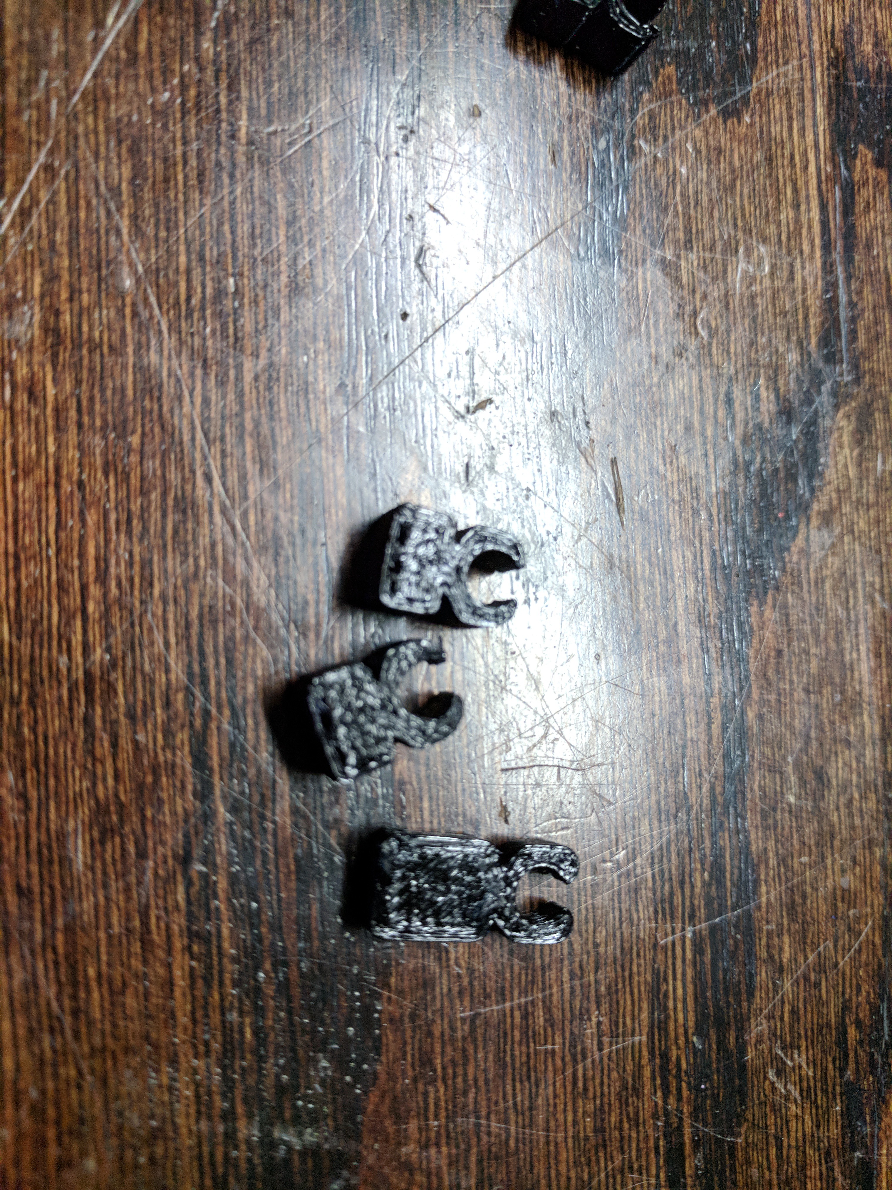
I also needed a way to stabilize the end / bottom of the vertical smooth rod, found a mount on thingiverse that someone made, but didnt fit right
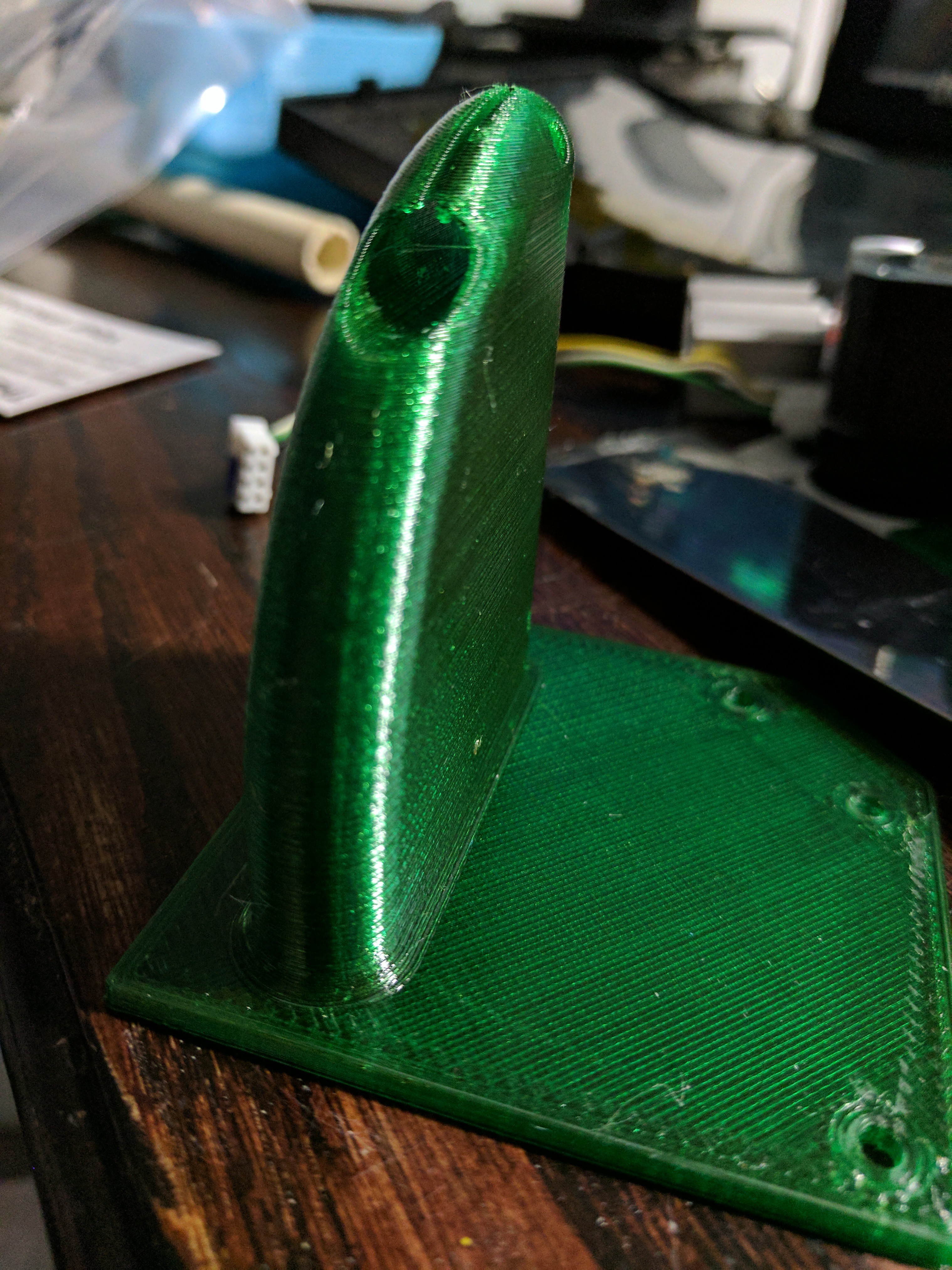
A few of my designs, until i got the right fit
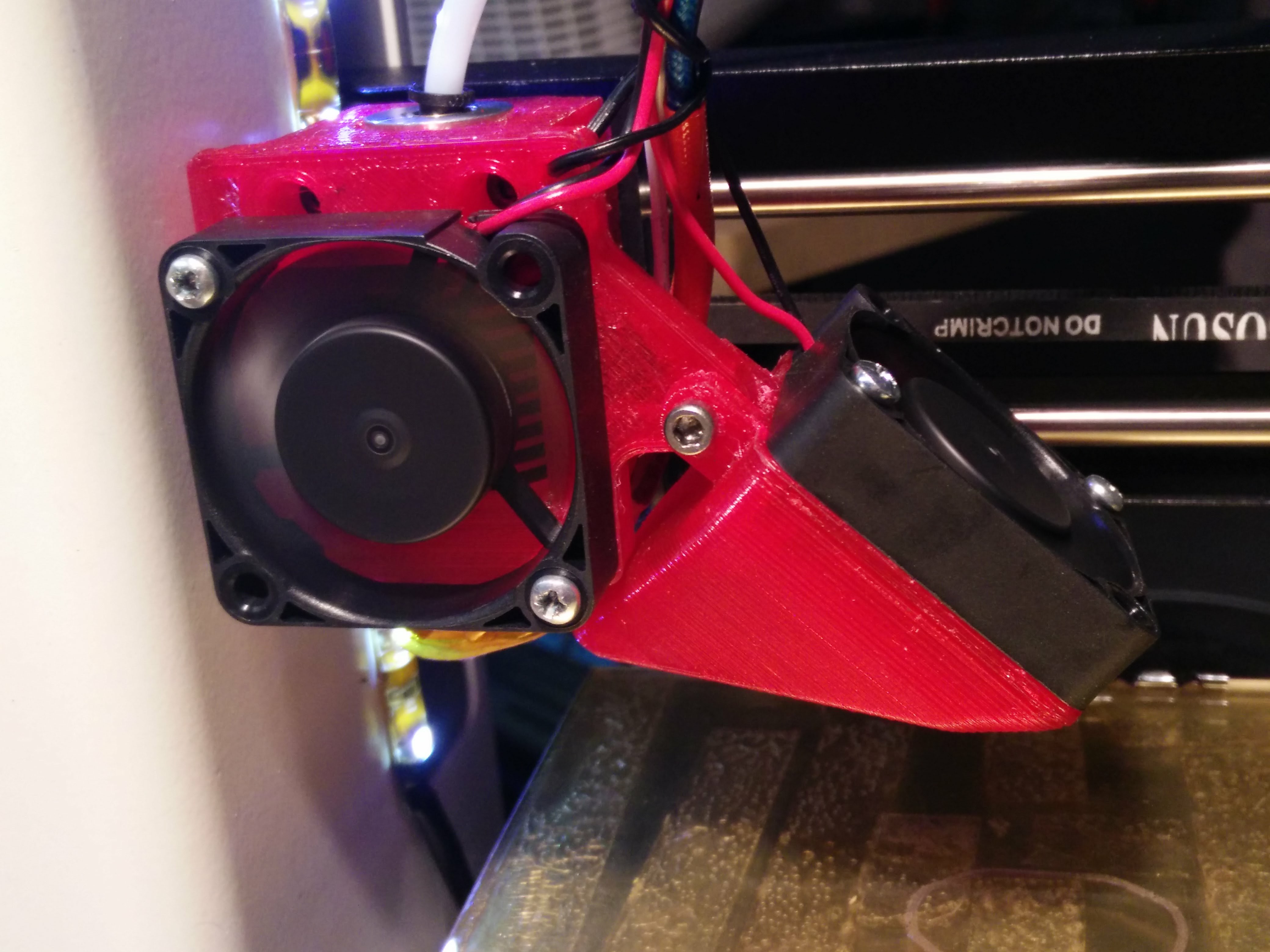
I also designed & printed a front section to hold the fan shown above. Then painted the whole thing with black plastic dip
I ran the printer for a while, until I came across a i3 acrylic clone for $50. I picked it up, made some modifications to it, & used that as my primary for a while since i could print about 200mm in Z, The mini was originally limited to like 120mm in Z i think, but with the frame/bed, I lost some height & i think I could only print like 80mm high..with all the big things i was printing from orders on 3d hubs, the mini was used less & less..then I came across a Flashforge creator Pro for $200. & picked that up. The mini was never used, & wasn't even connected for a while.
(random pics of said i3 clone & uprades & a pic of the FFCP) after theses,,,we get back to the minis modification...
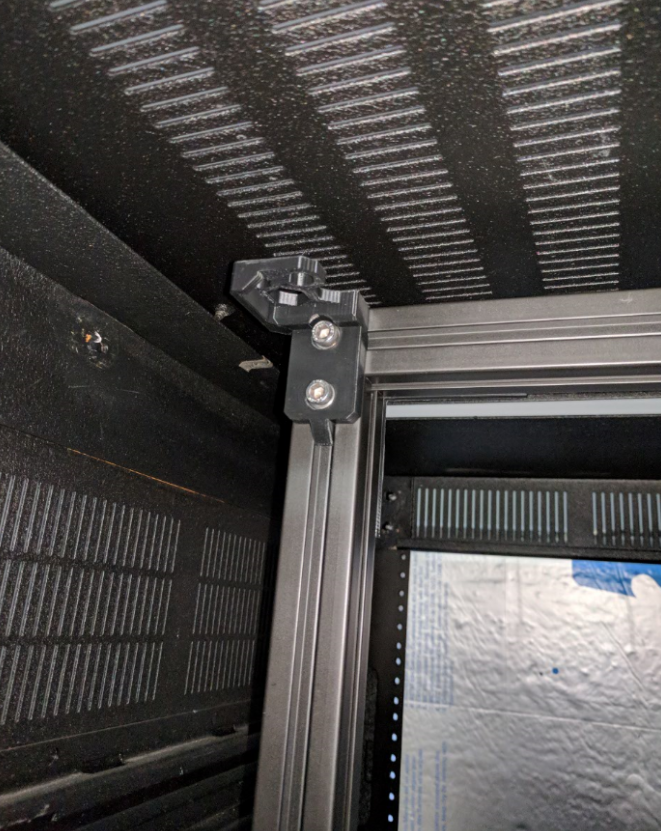
I have my printers in a 42u server rack (I have a build log on that coming as well) but the sunhokey wouldn't fit on the shelf/past the uprights if I sled the shelf out on the rails. The stock assembly for the tensioner was too large. I then searched a bunch of thingiverse pages for the sunhokey, downloaded countless assemblies, & once again none fit the way I needed to. SO I modified the parts to my needs & poof. now she pull on on the rails
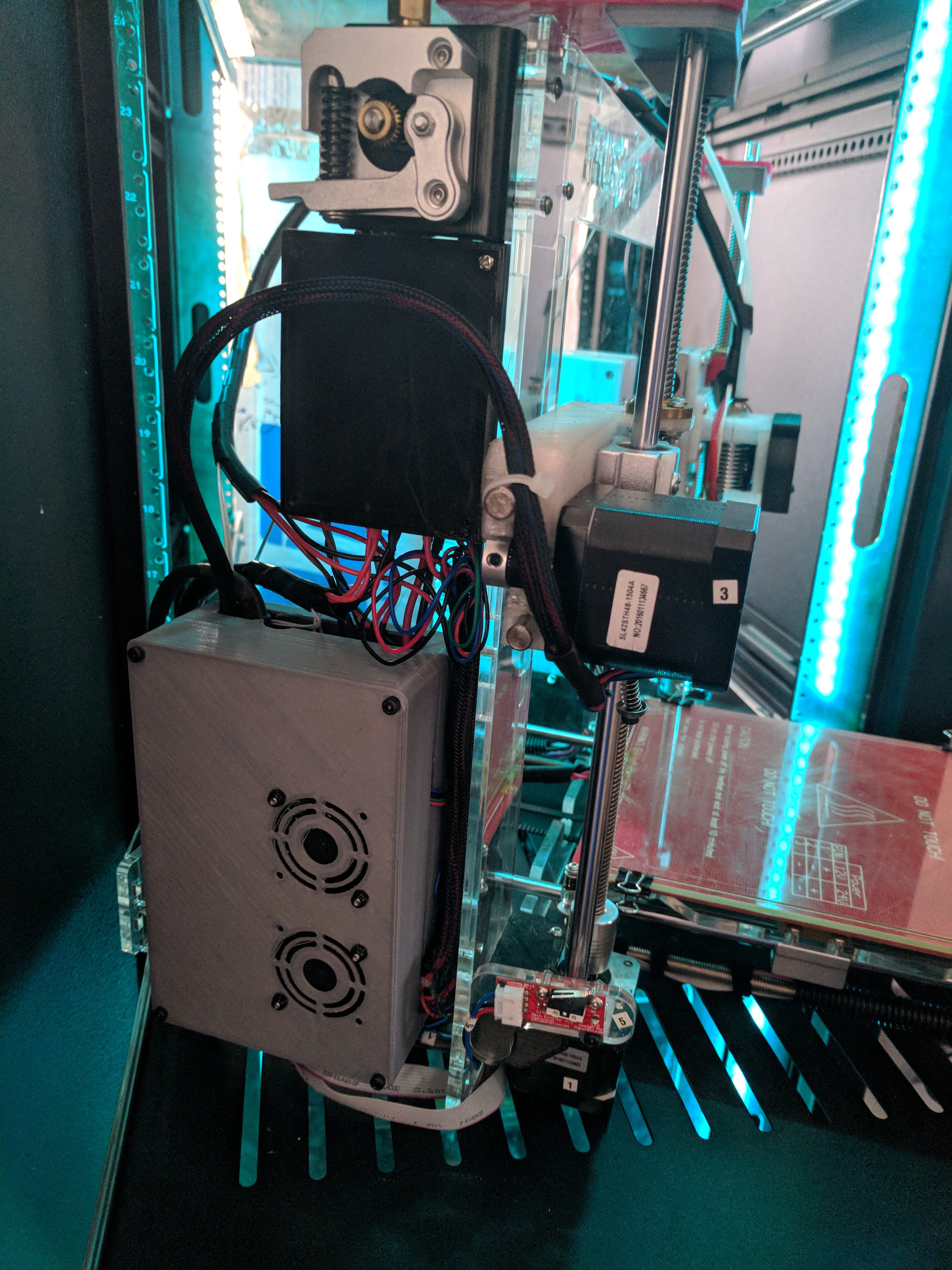
I have a issue with wires. At this time I was still waiting on my Engineer pa-09's to come in along with some connectors. So I just bundled & managed the wires as best I could
Black box is the mosfet for the bed, i couldn't do much with that tiny rats nest under it...but I've moved past it :)
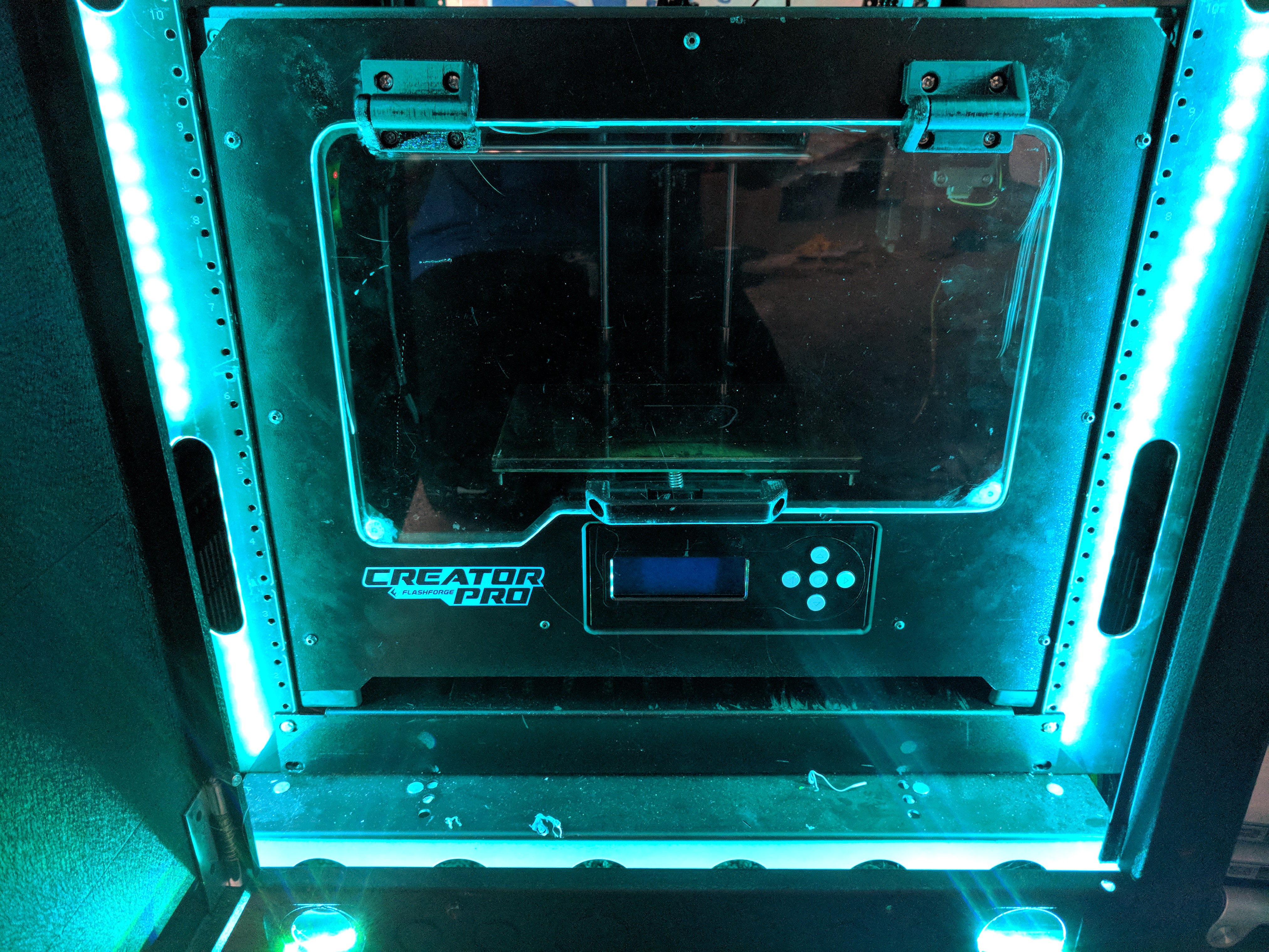
the FFCP
Ok, now back to our regularly scheduled program...
As time went on I had an itch to build another printer, wanted something fast, and large. So i began looking into what I could do...thought & almost pulled the trigger on doing a D-bot/core-xy system, but didnt.
I then had a side job that came up that yielded me some extra/free 3030 extrusion. I was on the hunt..I was looking for a frame/printer I could build with what I had...so basically as cheap as possible.
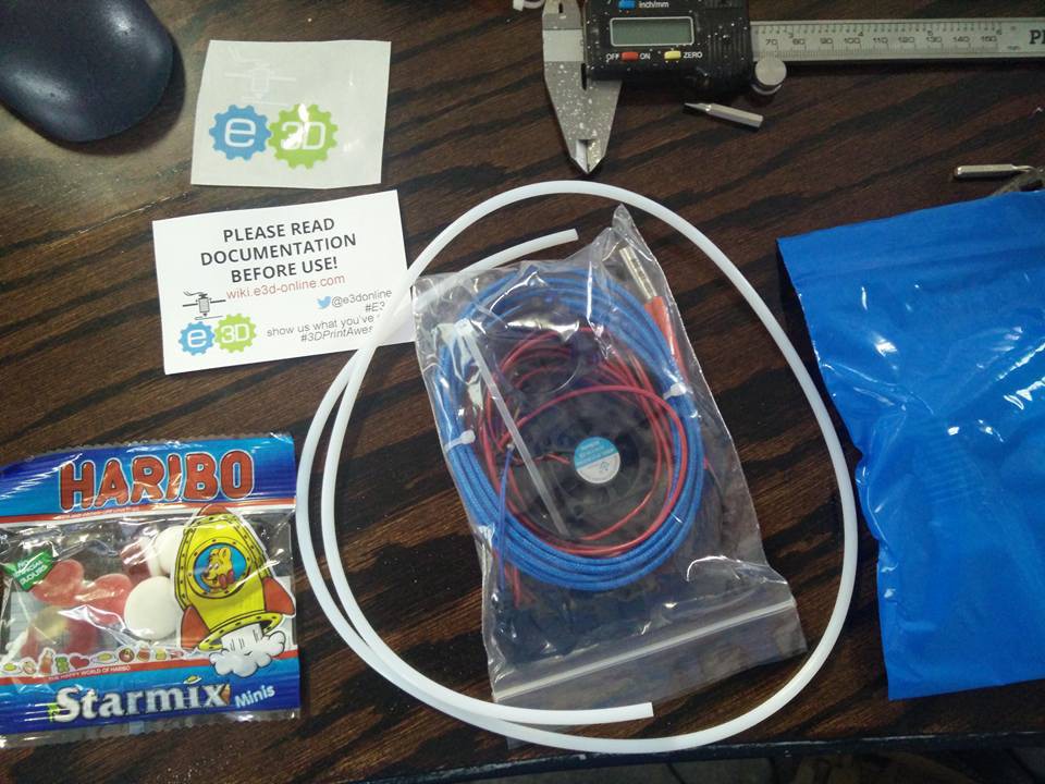
I first stumbled upon the folgertech builds, but for some reason I couldn't find a Bom or cut sheet, so kept looking...then I found a build on thingiverse for the MK-X (i think). While researching it, I came across the Haribo (https://github.com/PrusaMK2Users/3030_Haribo_Edition) which I was like "yup this is it"...however, then I found Zaribo build (basically the Haribo & Zaribo are identical, but the Zaribo is 320mmz & the haribo is 2xx something.)
I looked through the Boms, & determined I pretty much had everything I needed to build one of these, & really only needed to buy 2 more nema 17s for Z, 2 leadscrews, 1 more piece of alum extrusion & that was practically it.
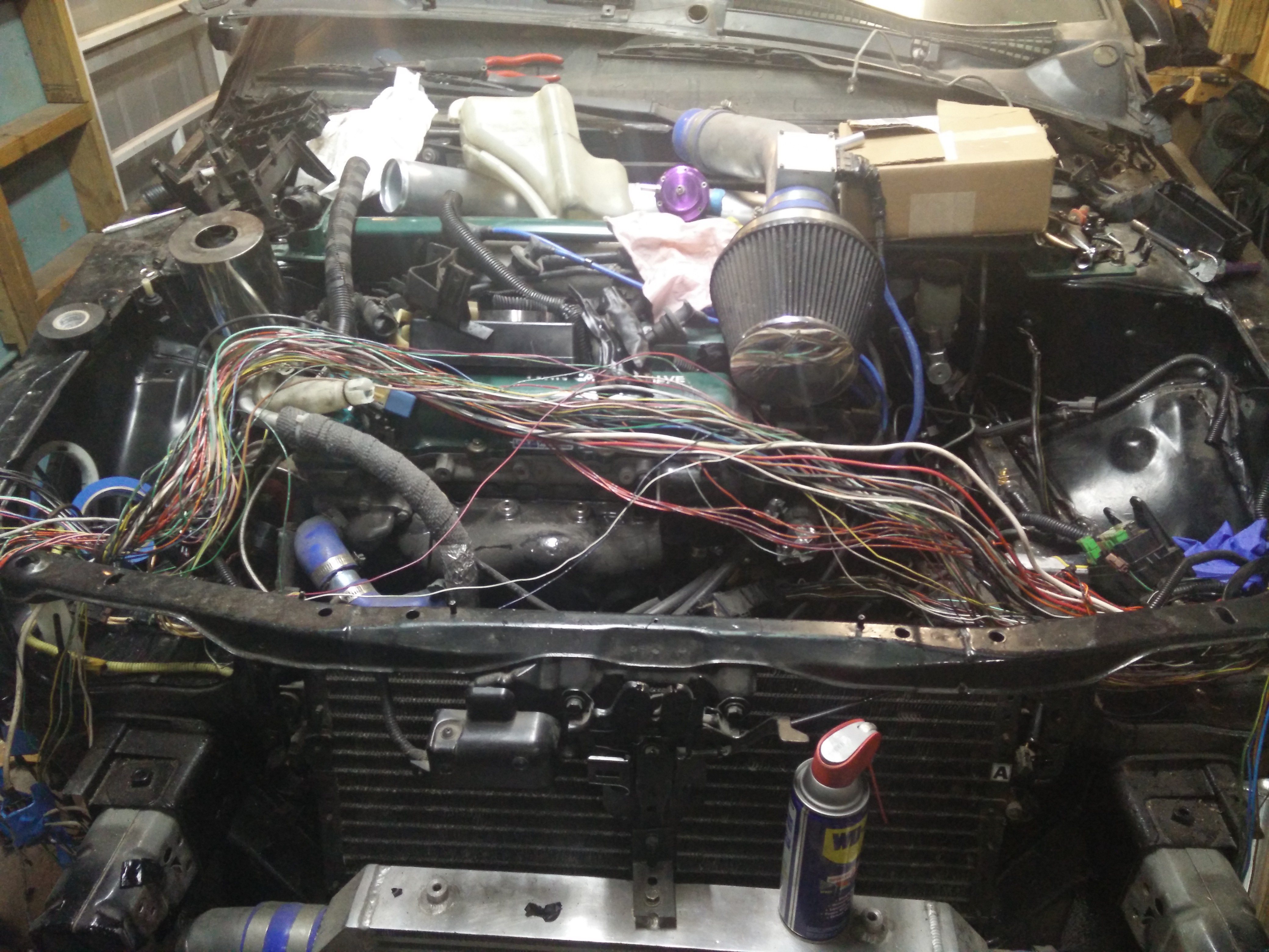
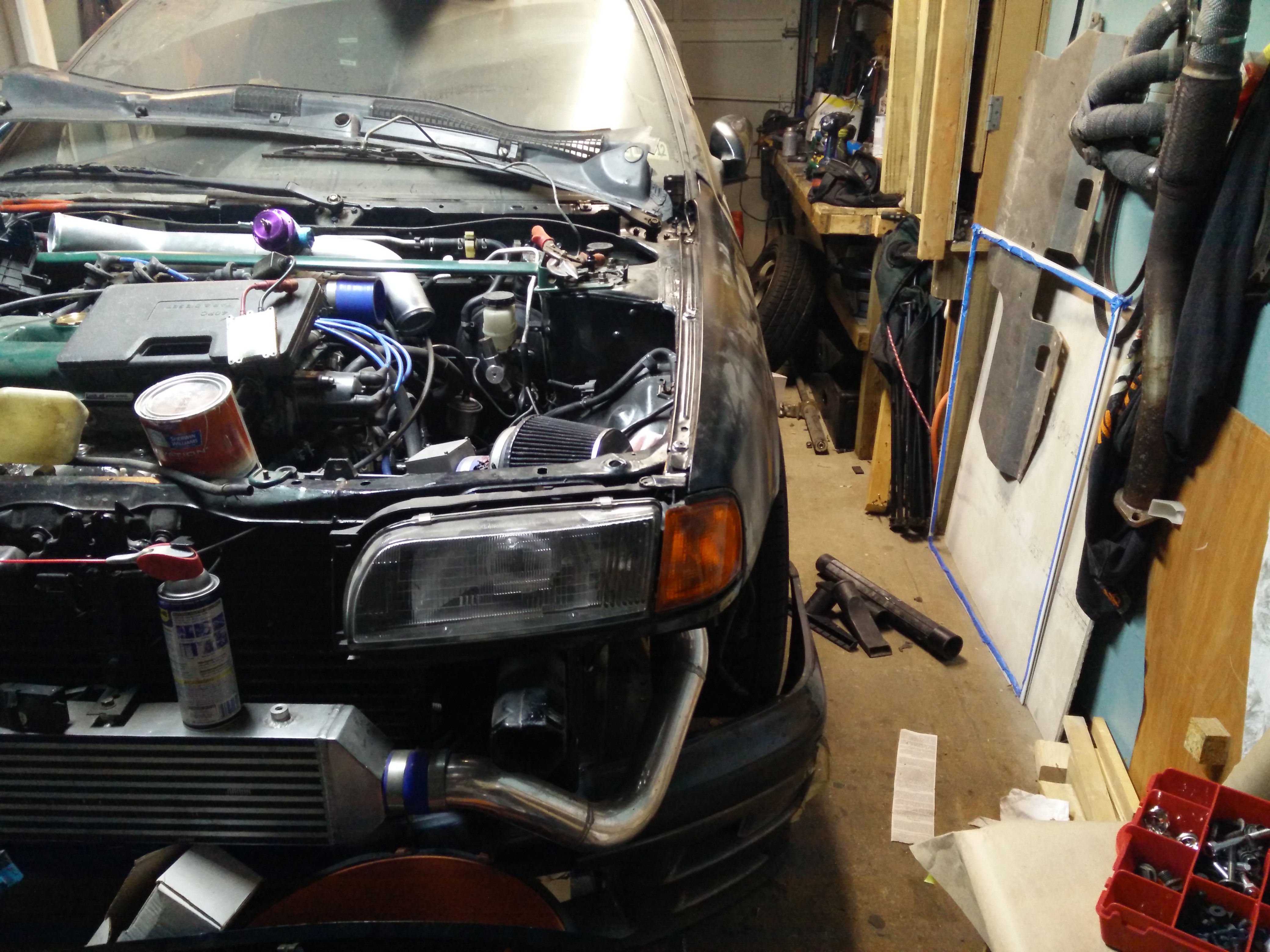
I began cutting my extrusions. (FYI Misumi is awesome, you can order from them pre-cut/drilled etc. I highly recommend them) However I had a few very long pieces, so on my VERY cluttered /cramped bench on the wood working side of my 1 car garage
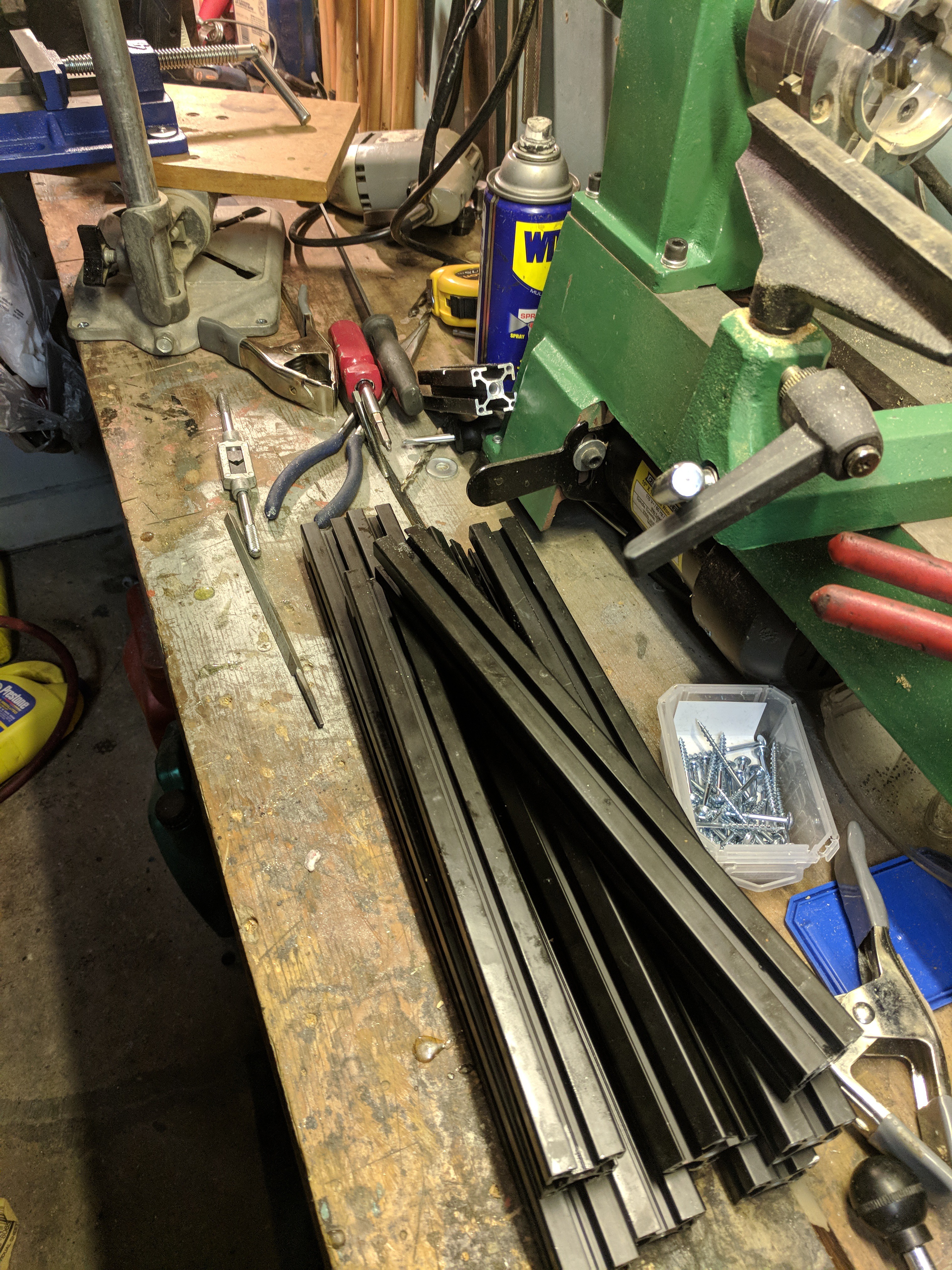
it doesn't look like it, but there is only like 2 feet between the edge of the bench & my race car Im building (been building it for last 5 years,,,I had a kid & kind of stopped working on the car)
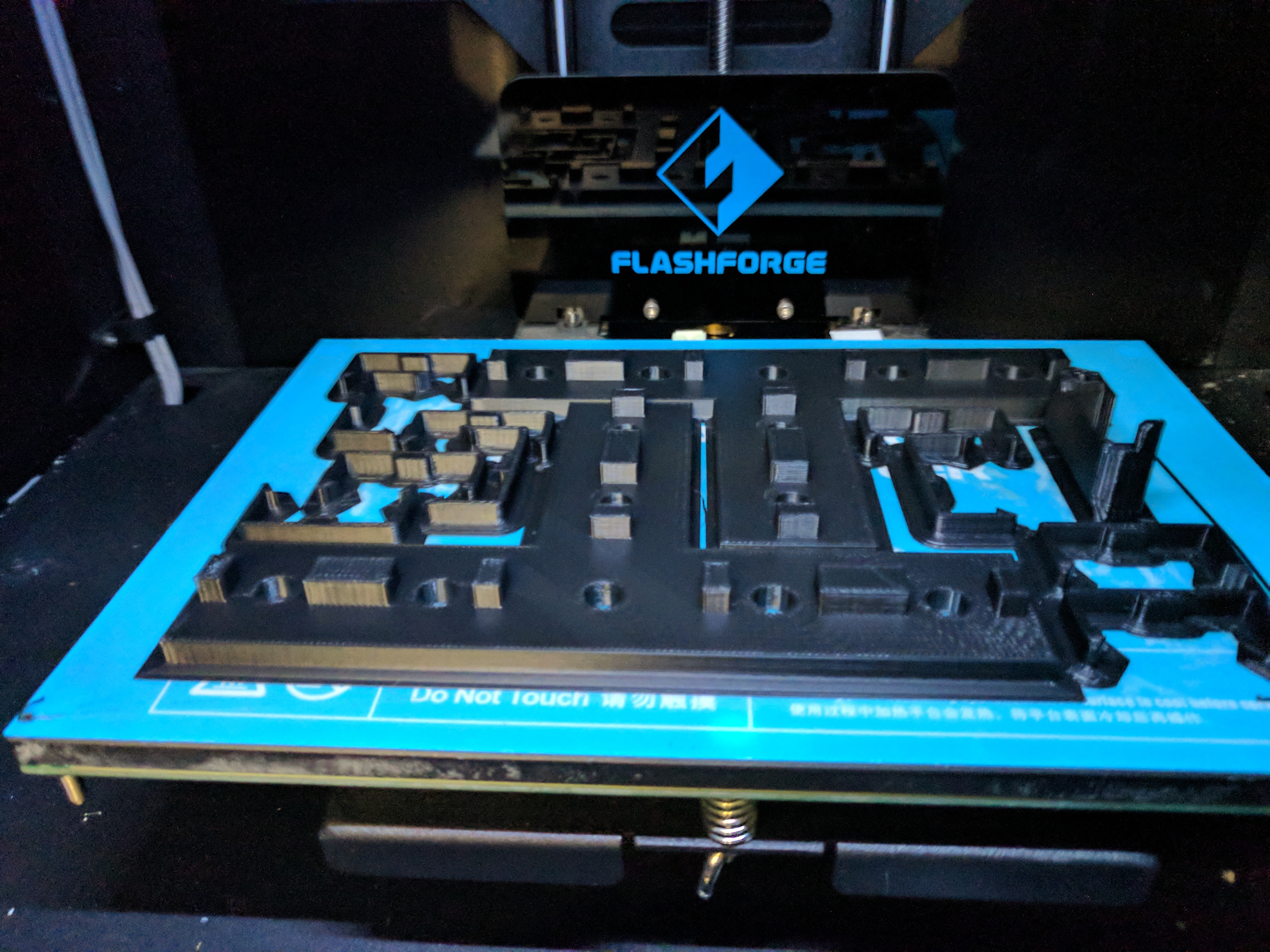
With the pieces cut, & my holes drilled, tapped & counter sunk. it was time to print out the the frame pieces & other random plastics needed for the build. I printed on my FFCP in PETG, 3 walls, 3 tops/bottoms & around 30% infill (it varies between each piece)
The first Issue I ran into, was the X/Z plastics that hold the smooth & lead screw didn't fit my setup. as they were designed to fit the Stock Prusa POM/delrin nut they use. I had a standard brass nut. After looking & printing about 4 different setup, I found 1 that worked perfectly in terms of spacing between my smooth rod & lead-screw & the top mount & lower/motor mount
(https://www.thingiverse.com/thing:1103976)
With all pieces printed it was time to assemble
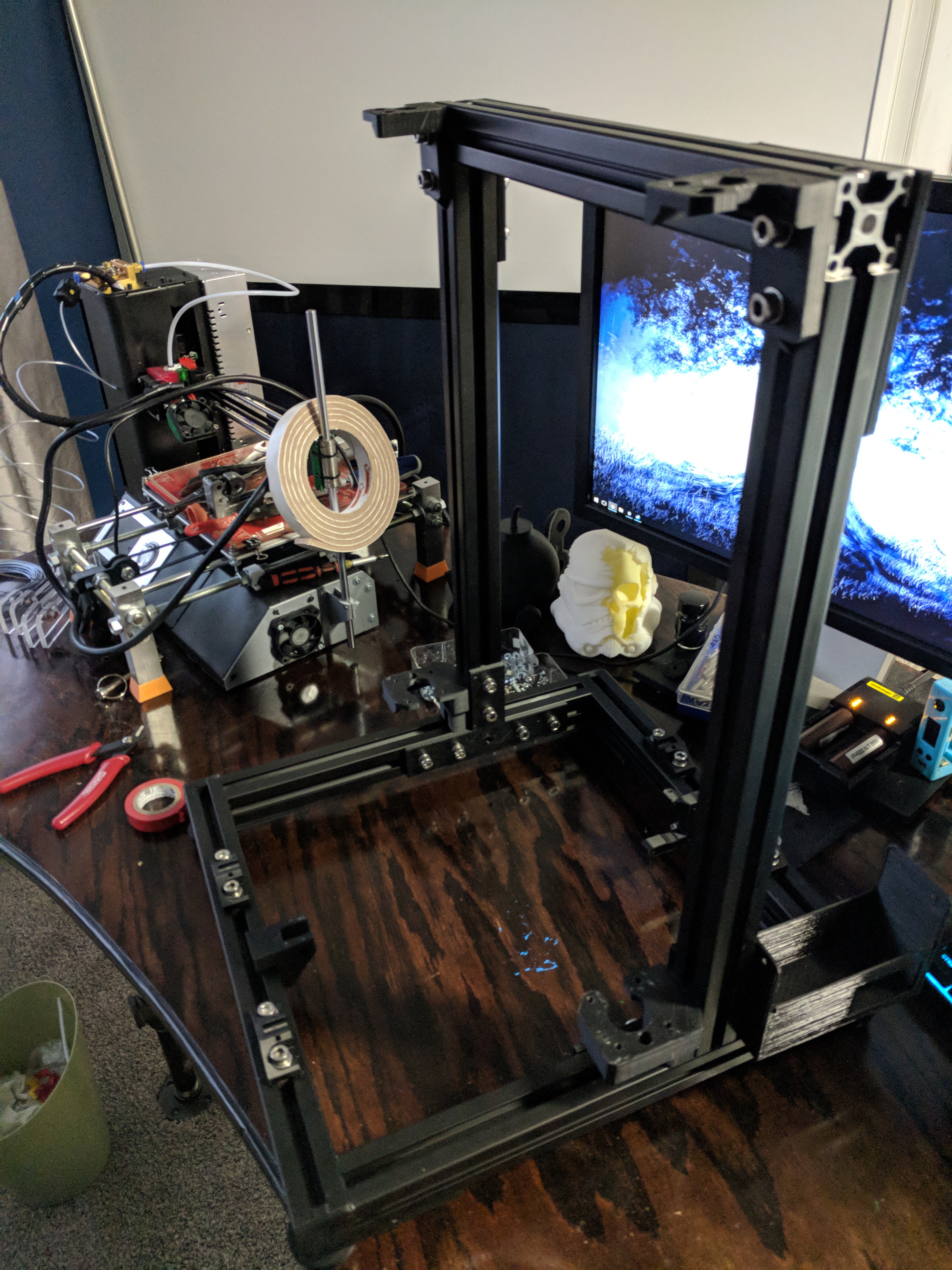
testing if it fits in my Rack, just barley...however I have to cut my lead screws first as they stick out a few inches past that top mount
being that I want using ANY prusa parts I had to design a few things to work with the minis stuff.
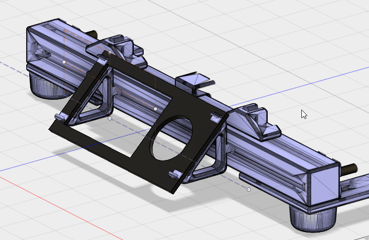
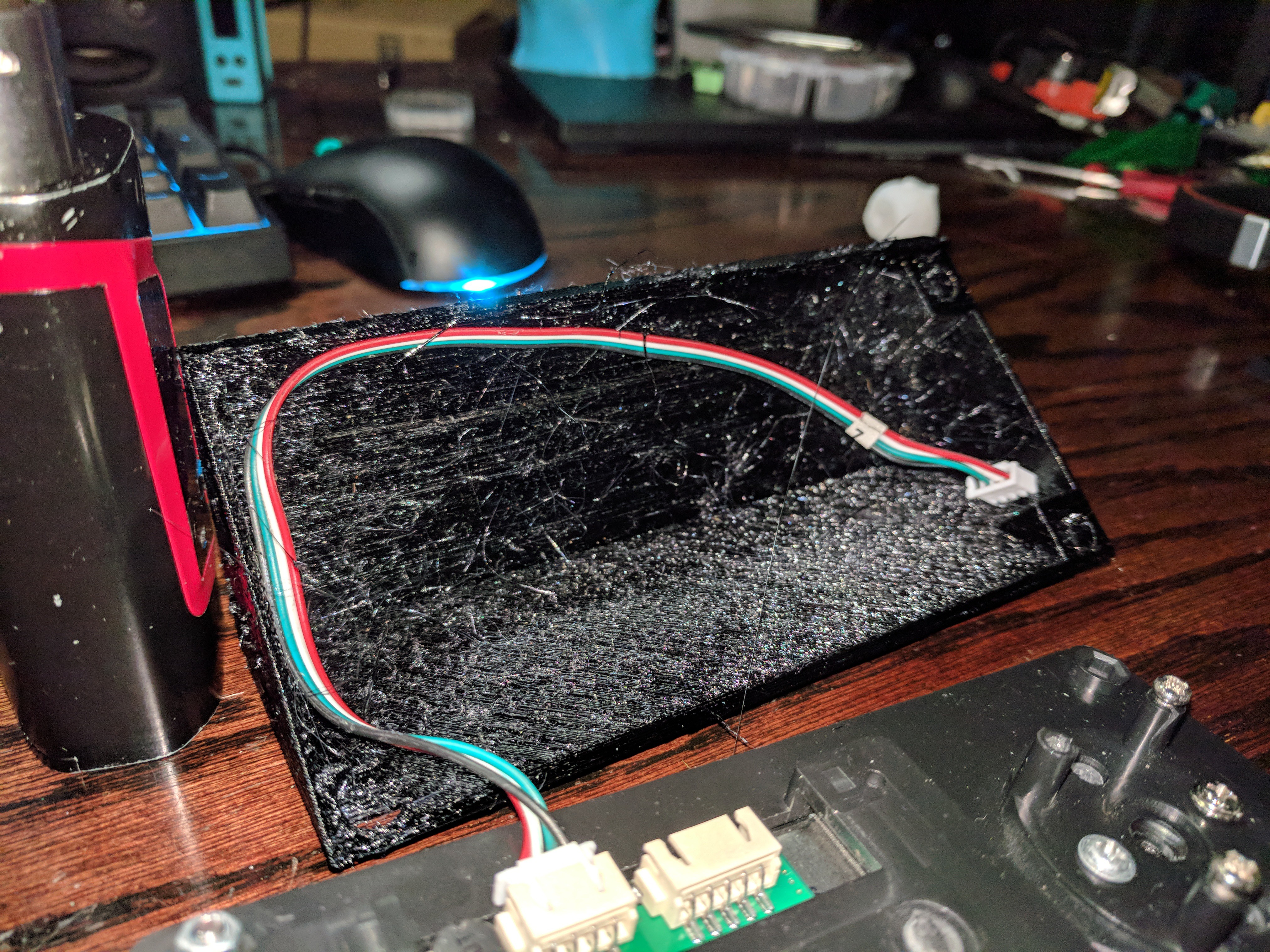
first was the LCD assembly, planned on using the minis Lcd & obviously couldnt find any pre-built models of mounting the LCD to a 3030 frame.
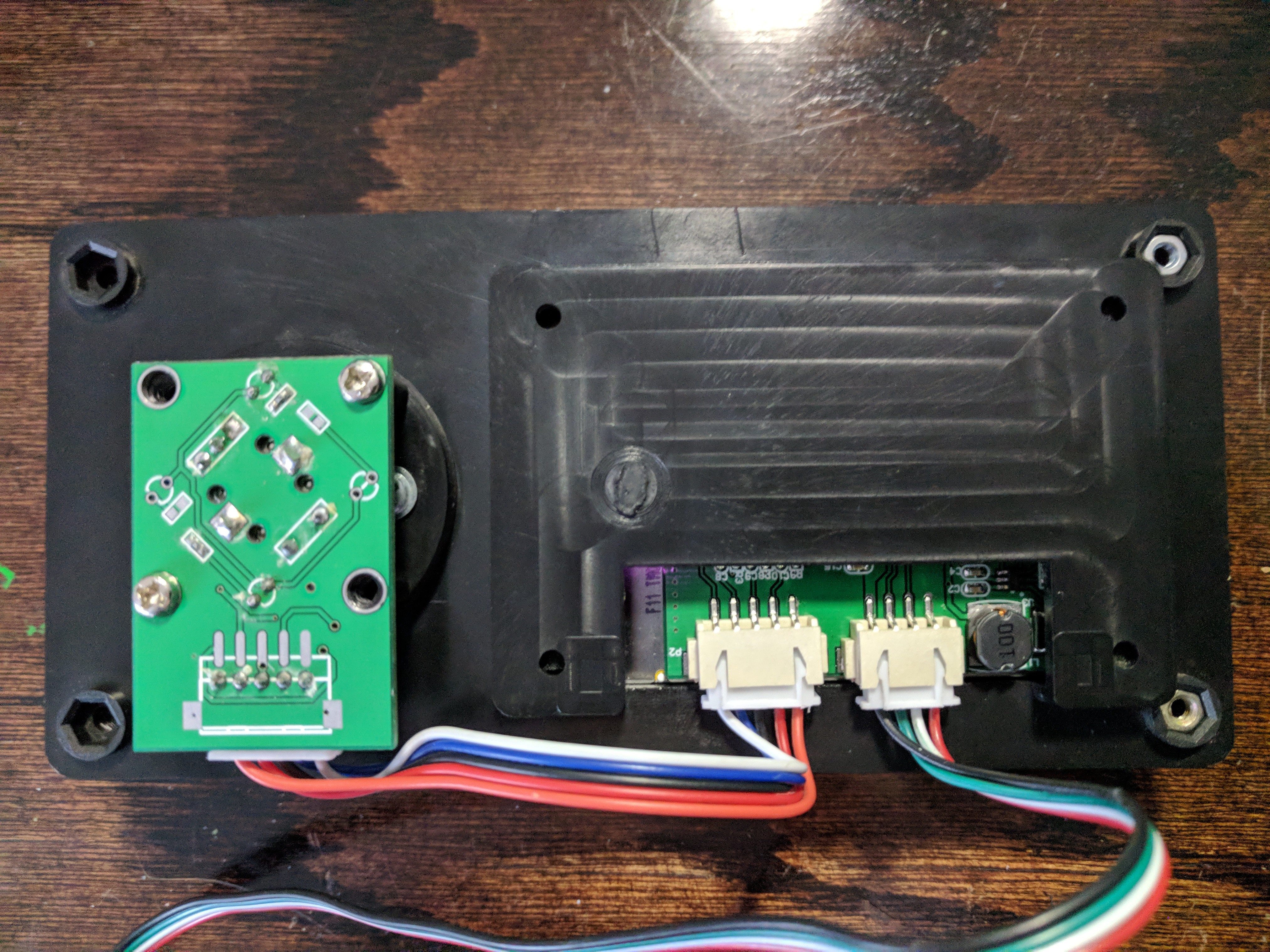
I took some pics of the LCD assembly & imported them into fusion to begin digitizing it
I have very little exp with 3d design. this printer was the first time i really touched it, so it was a pretty steep learning curve & time gap between me starting this aspect of the build & then finishing it. (2 months or so)
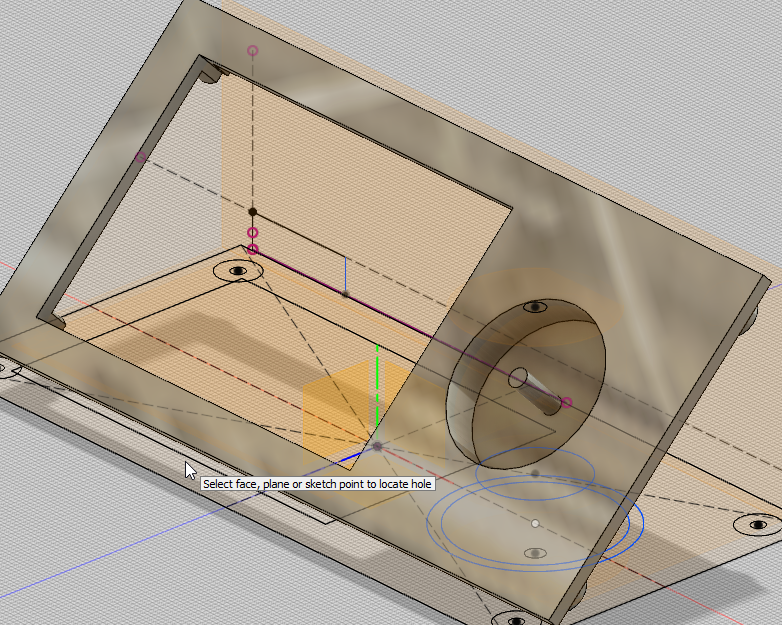
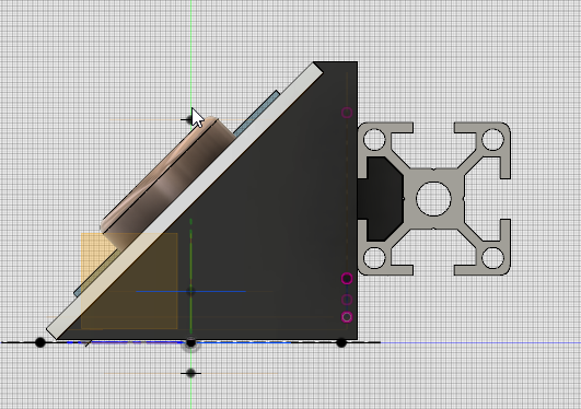
With the pics imported into fusion, I started making some sketchs & extruding them out & playing with them a bit
I imported in a Haribo frame STL someone made for like cura or simplify 3d , & cut the front end off to begin my mock up. H
at first I was going to use the clips that are used to hold the normal character based LCD that most 3d printers have, but I didn't like the way it was looking
I then decided that it would be best if I modeled the entire LCD, & then made something work for me in terms of mounting
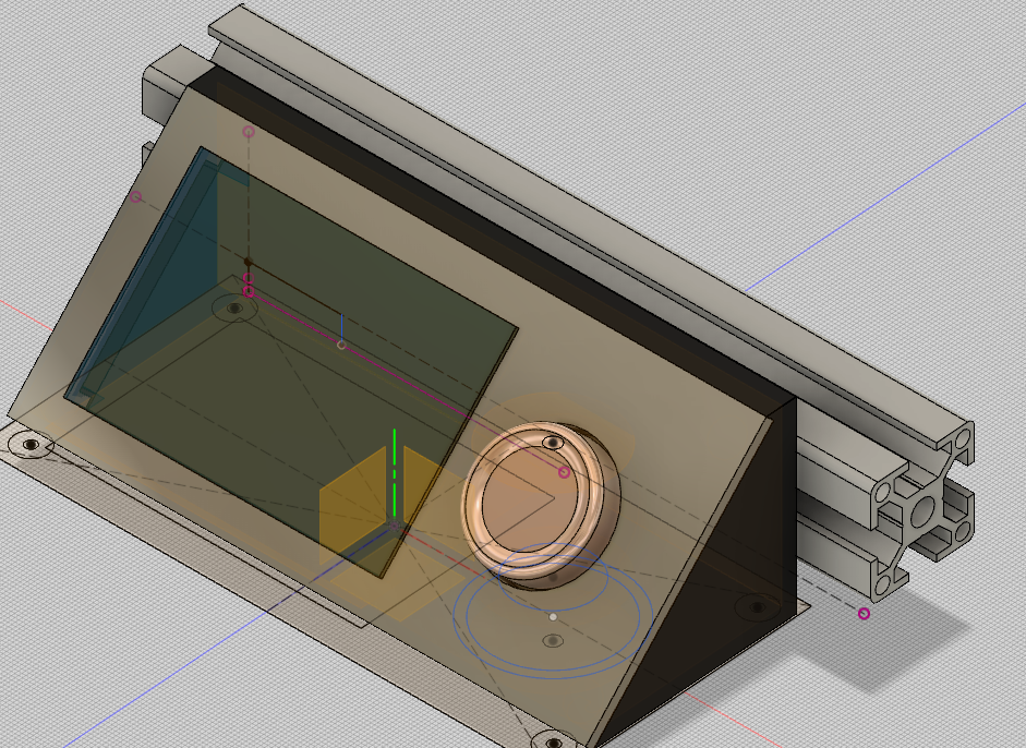
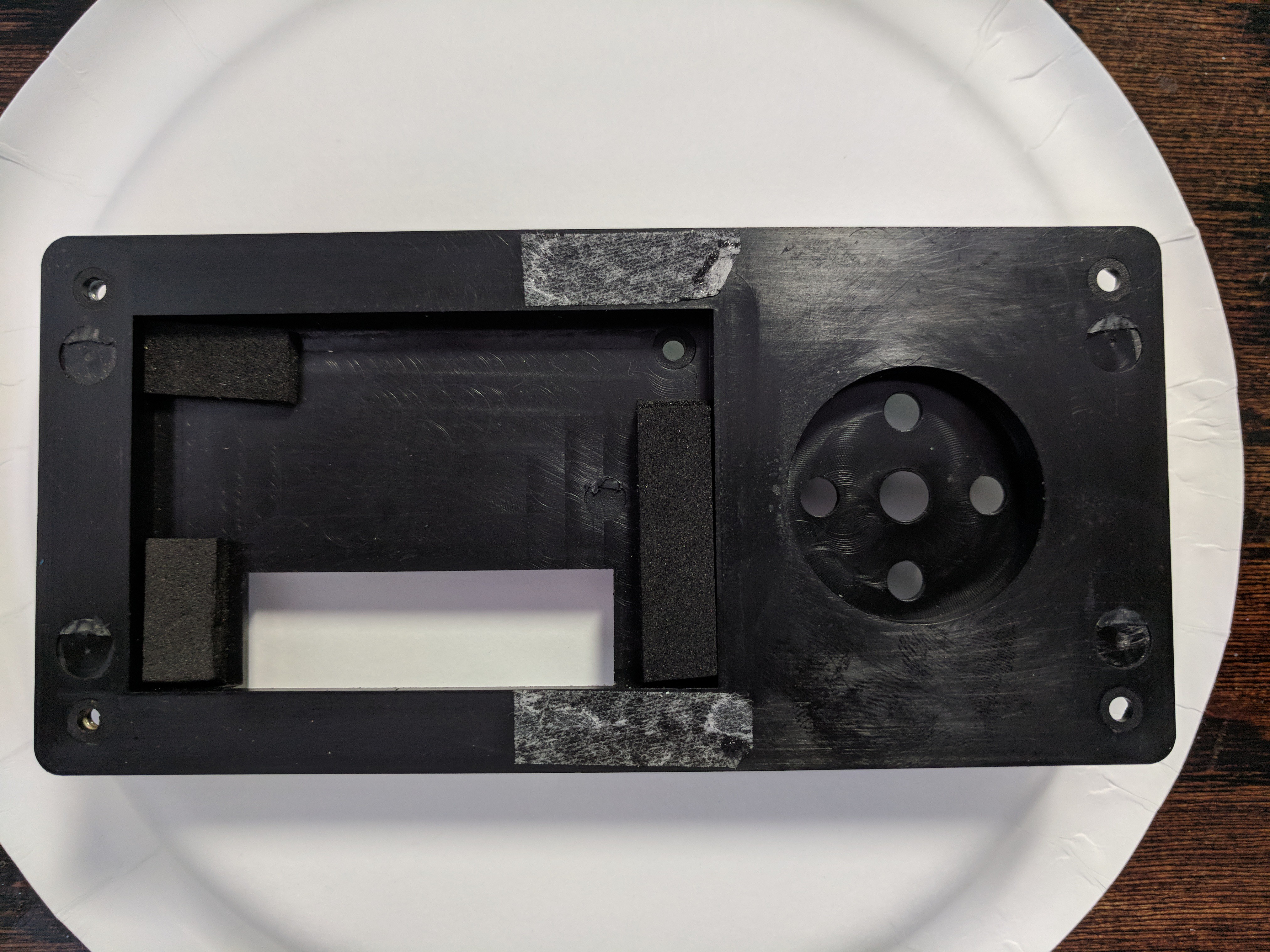
With this all modeled, & mocked in digital life, I then printed it out
It came out....ugh hairy?...apparently I left my PETG out & it was a bit humid so it absorbed a bit of water, causing my retraction profile to not work correctly, but I didn't care,.this was print 1 mock up @ 2.5 or 3 mm heights
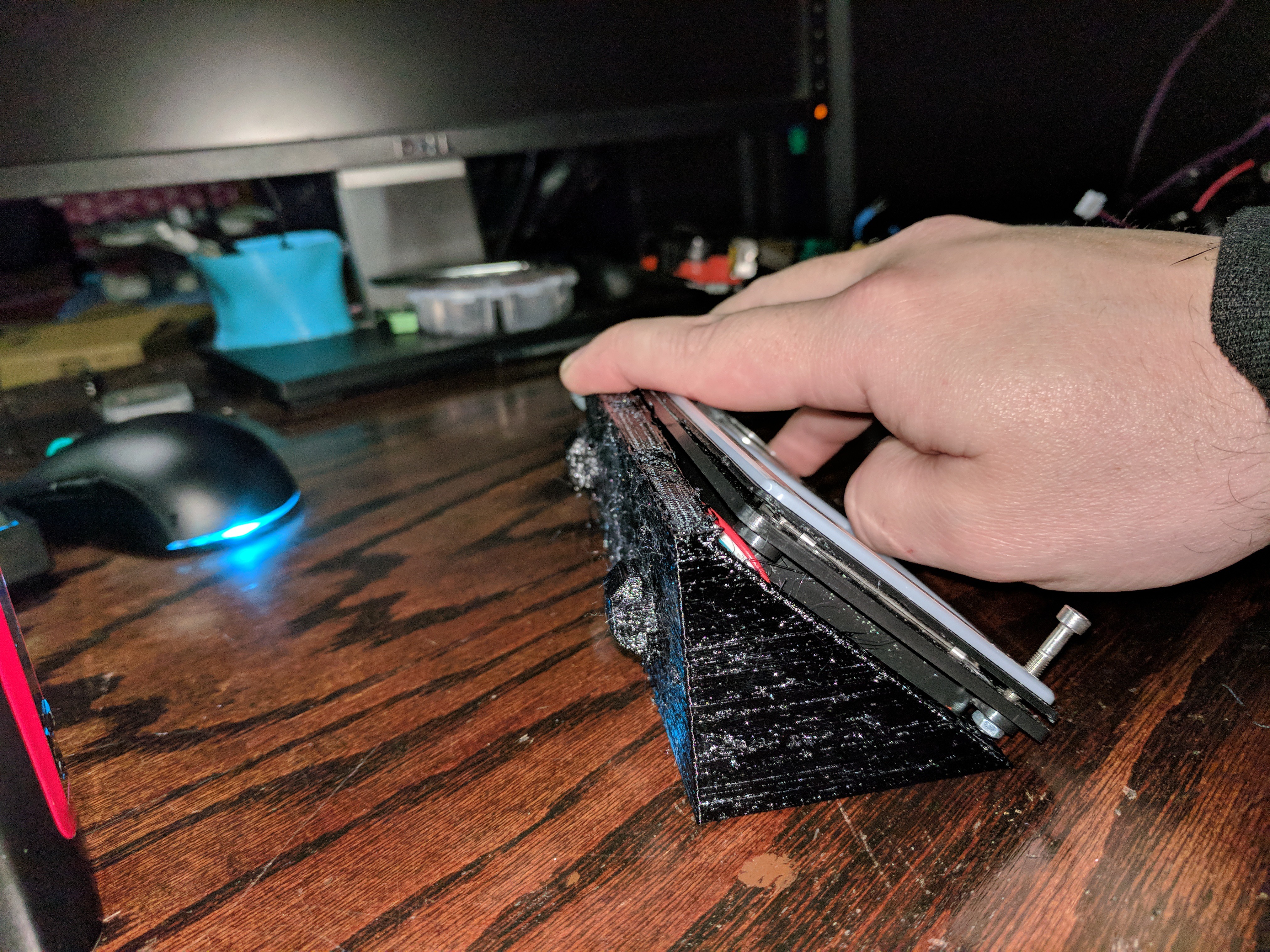
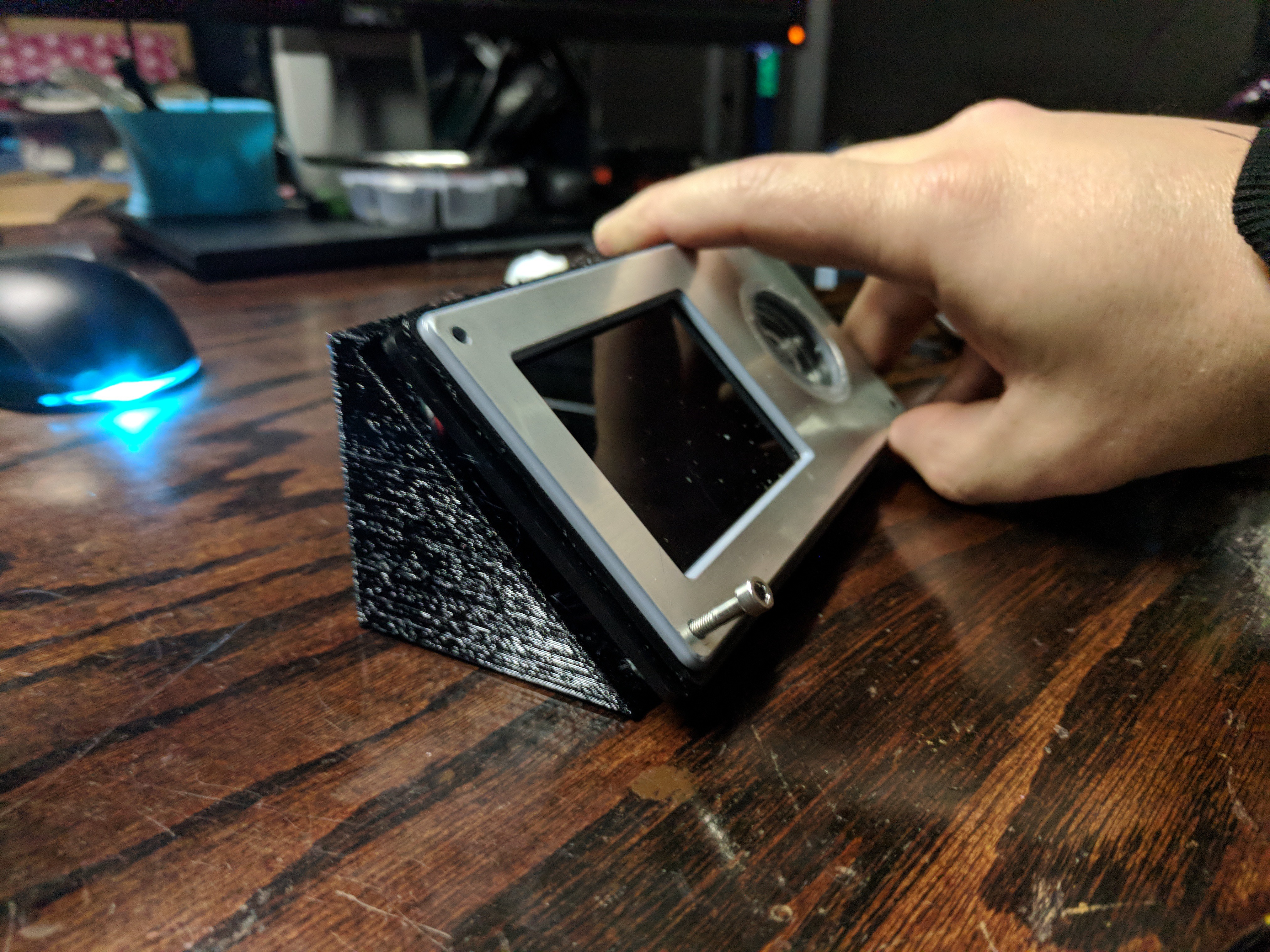
first print was a bit off to mount the LCD, but the other dimension were spot on (the tabs for the extrusion, how it sat on the extrusion, etc...just the LCD mounting holes were off/hit So i adjusted, & also added a cutout in the back to allow the wires to pass through
While the new LCD case was printing I started mocking up my electronics layout. (side note. I didn't want to have my stuff mounted to the outside of the frame /visible & thought that I had more then enough space to mount everything UNDER the bed, I took a piece of 1/8 ABS I had, & cut it out as a bottom for the printer, drilled holes & put in standoffs to hold everything
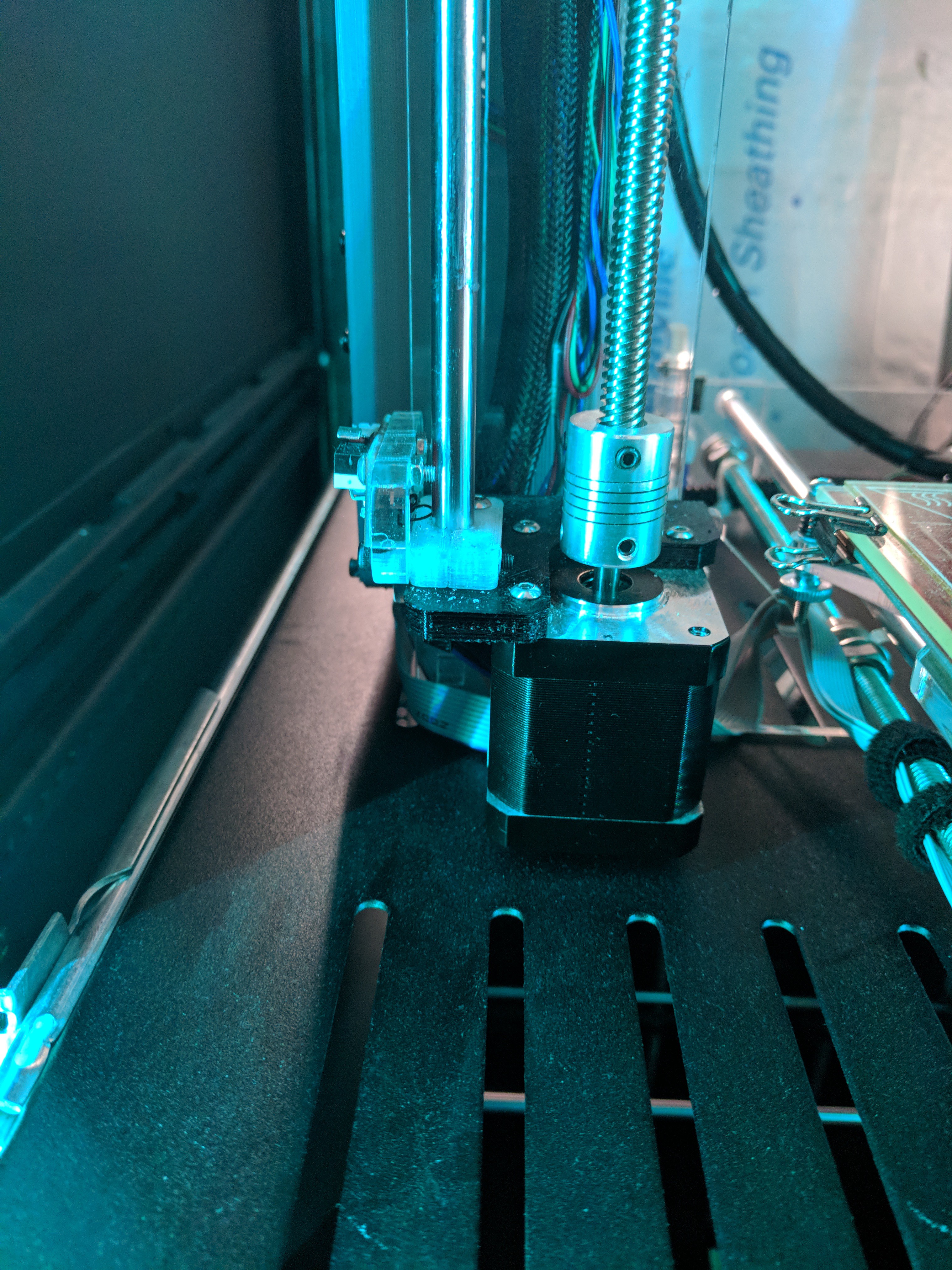
The boM calls for motor with Integrated lead screws...Well I couldnt find any as long as i needed & also that didnt require a month+ wait to arrive. I bought some standard motors, separate leadscrews & some flexible couplers.
I assemble everything do some manual test & realize that the stock x motor holder & X tensioner mounts hit the couplers when the X setup goes to the bottom. At this height I would have lost about 30mm of height & wasn't having that.
I took some measurements of my clearances, order me some rigid couplers hoping they would fit...
they didnt.....
\
over to my Wood lathe they went (yes, wood lathe, I dont have a fancy metal one)
(not sure if this link to the video works but here goes)
https://photos.app.goo.gl/8SN7bzsNW4kvDOwf1
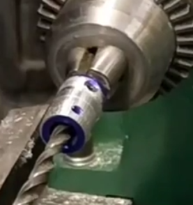
I turnt the couplers down to an appropriate size & polished them up. (I went back to the lathe 2 more times to get them Just right.)) I Also had to cut the set screws down, as they would hit the X mounts as well. this turned out to be more of a chore then I thought it was going to be
We now are faced with the largest challenge so far...how to power the 2 Z motors I was now running, since the minis controller only supports 1. Back to the Internets...
I recalled reading on a rep-rap forum that some/a few controllers supported running 2 z's in parallel or in Series. I then began the track of trying to figure out if the mini's board could support either of those configurations, unfortunately their info on their 32bit controller at the time of doing this was non existent. Being I had a spare RAMPS setup lying around, I figured WTH just try it..If I burn out the mini controller o well. Then I tried to figure what would be best series or parallel
I decided to go with Parallel since it was quicker/easier for me to do this Vs building a Y splitter for a series circuit.
I did a test run & all seemed fine...after this I had it run some basic up & down commands for a few hours & kept checking on everything. After a 20hr of 300mm up's & downs. I decided to leave them in this configuration
https://photos.app.goo.gl/R9ilc8OUG1sUM23U2
Next hurdle was the exturder setup. I was planning on doing a direct drive setup using the stock Prusa MK2.5 parts, but my hob gear /extruder setup didnt line up correctly with the Prusa Mount, So I decided to go with a bowden setup
I designed & printed a motor mount for the top of the frame. But the handle of the exturder was hitting the frame, so I took it off, went to my band-saw & cut if off, now it doesn't hit :)
Next was some other wire management stuff. the haribo & Zaribo plans, have you put the T brackets on the inside, however I place mine on the outside of the frame, this way I could use the channel in the extrusion to run wires to keep things a bit tidy (did I mention I hate wires showing?)
designed & printed some standoffs for some of the wires
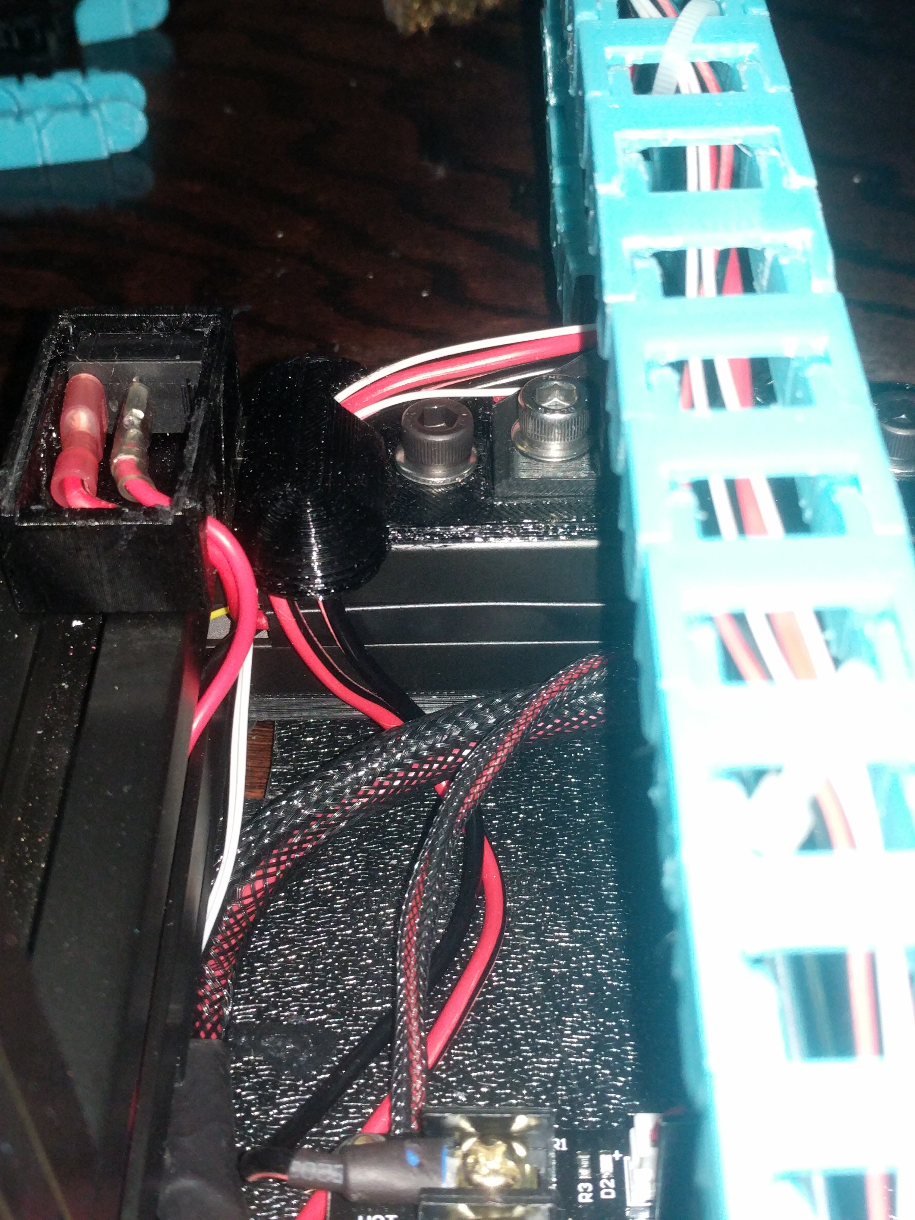
Now that the wires "inside" the base of the frame were looking good. I moved my attention to the wires on the backside (power, hotend, bed, etc)
I wanted to independently control the power to the printers controller separate from the power supply
The way it is configured is:
Power-supply runs to a switch for the mains, then from there runs to another switch for the 12v for the printer power. I also have direct power from the power-supply powering LEDs & a fan for the controller that are not operated by the Printers power-switch (IE. they turn on when I power-up the power-supply)
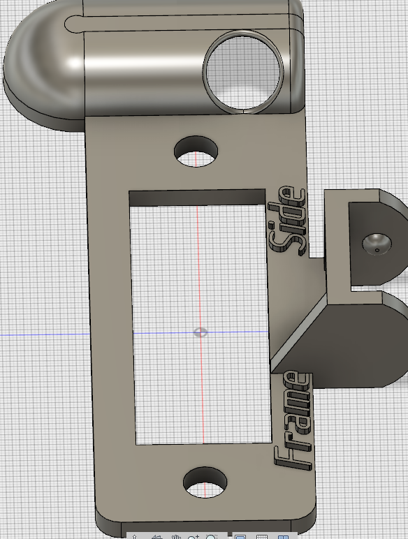
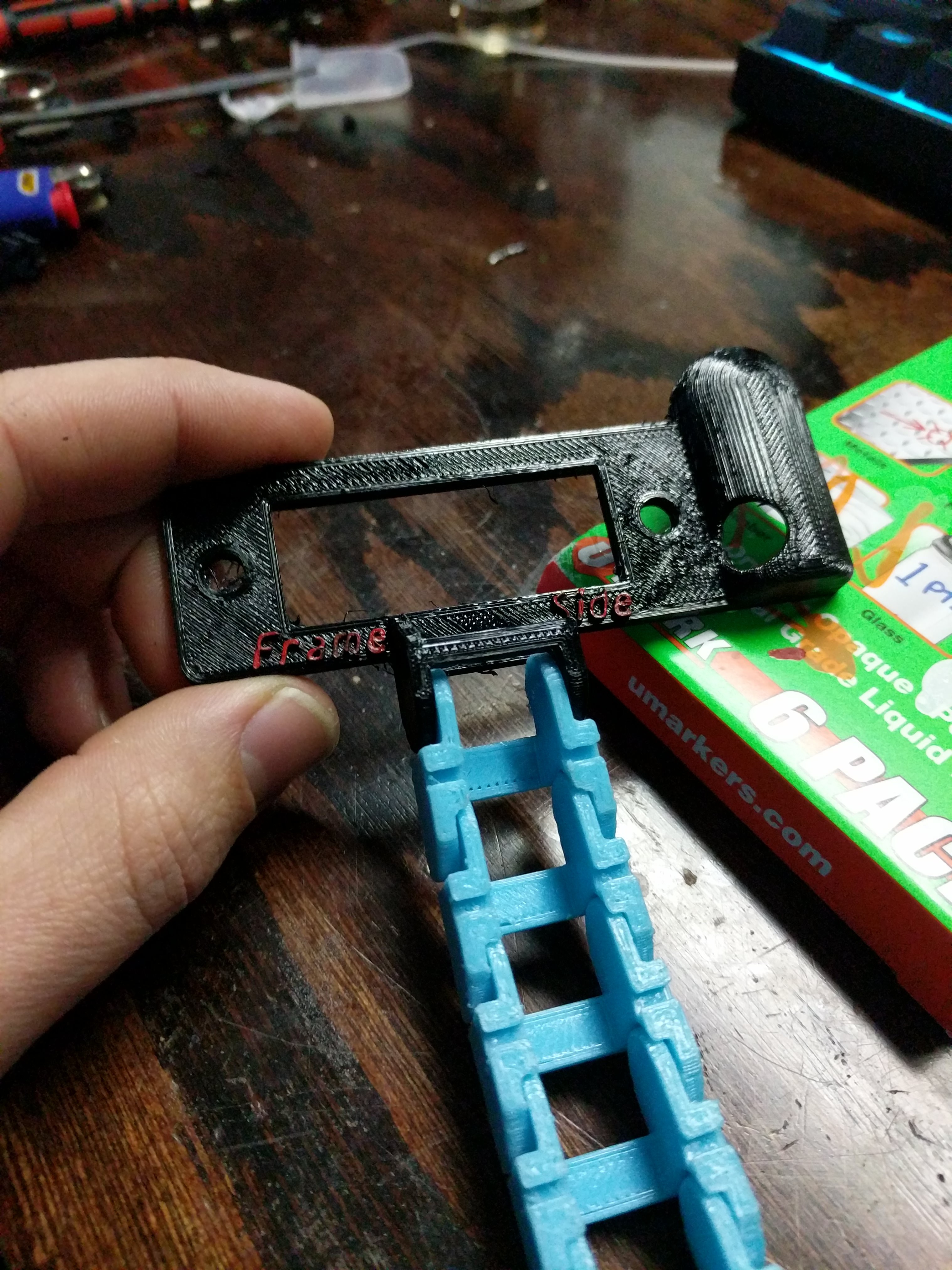
I designed a housing for the switch
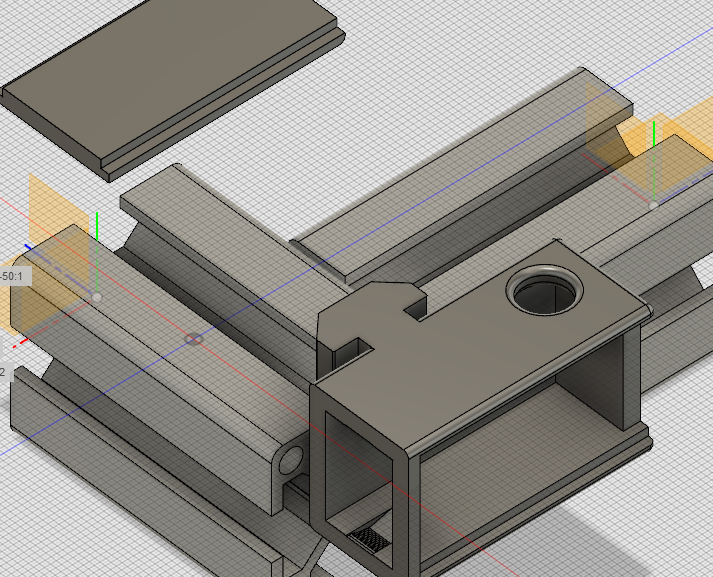
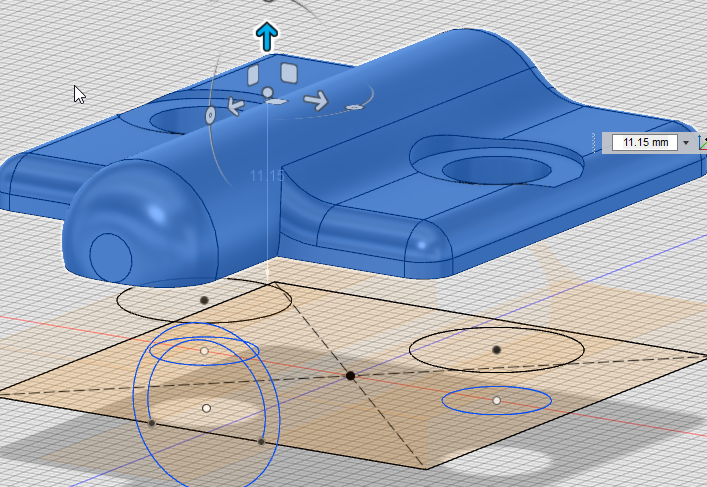
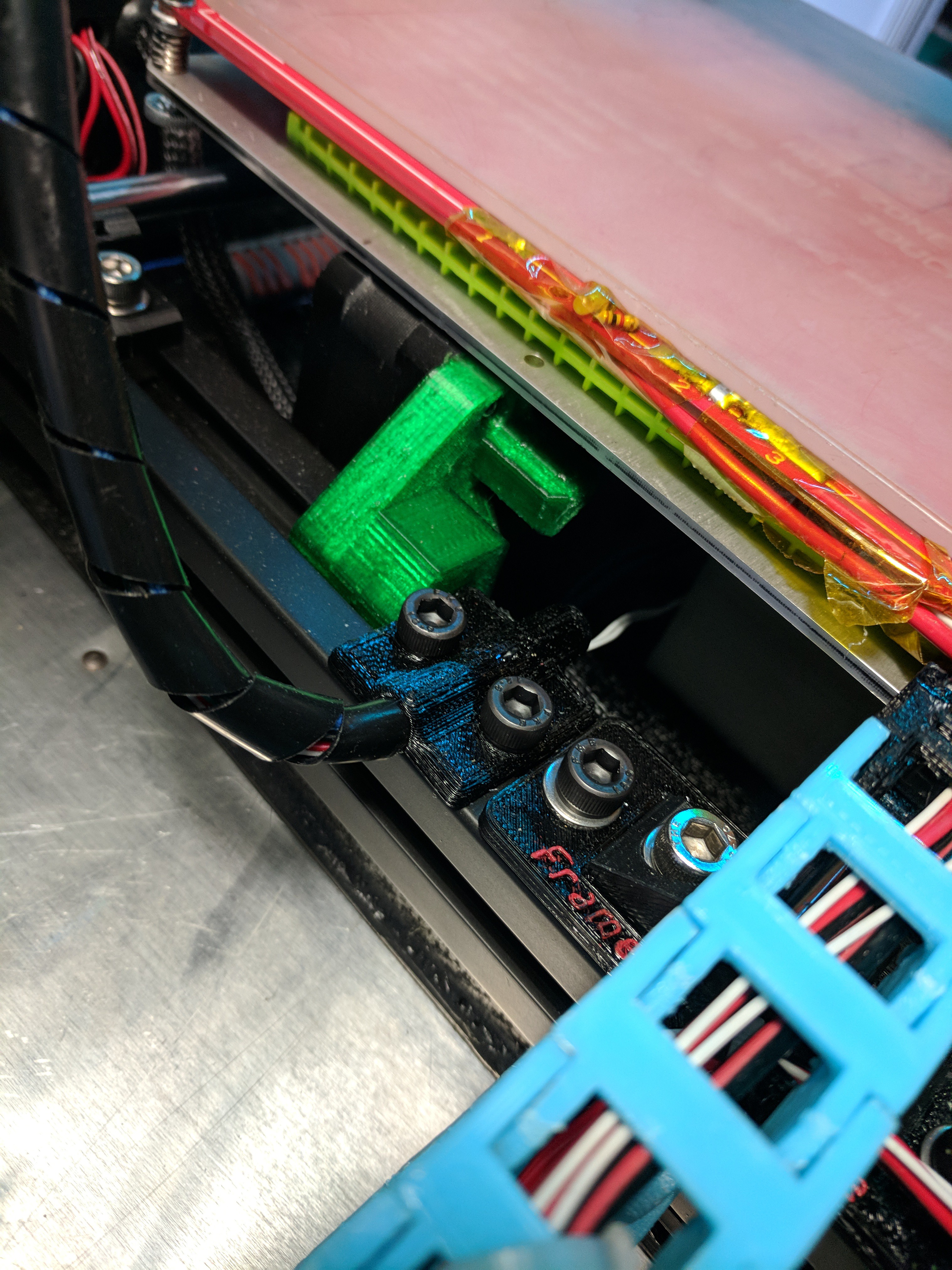
I then focused my attention on the bed wires. I needed something that would route the wires where I wanted, & also allow me to mount a cable chain
back to fusion 360 I went
After about 5 different versions, I ended with this one
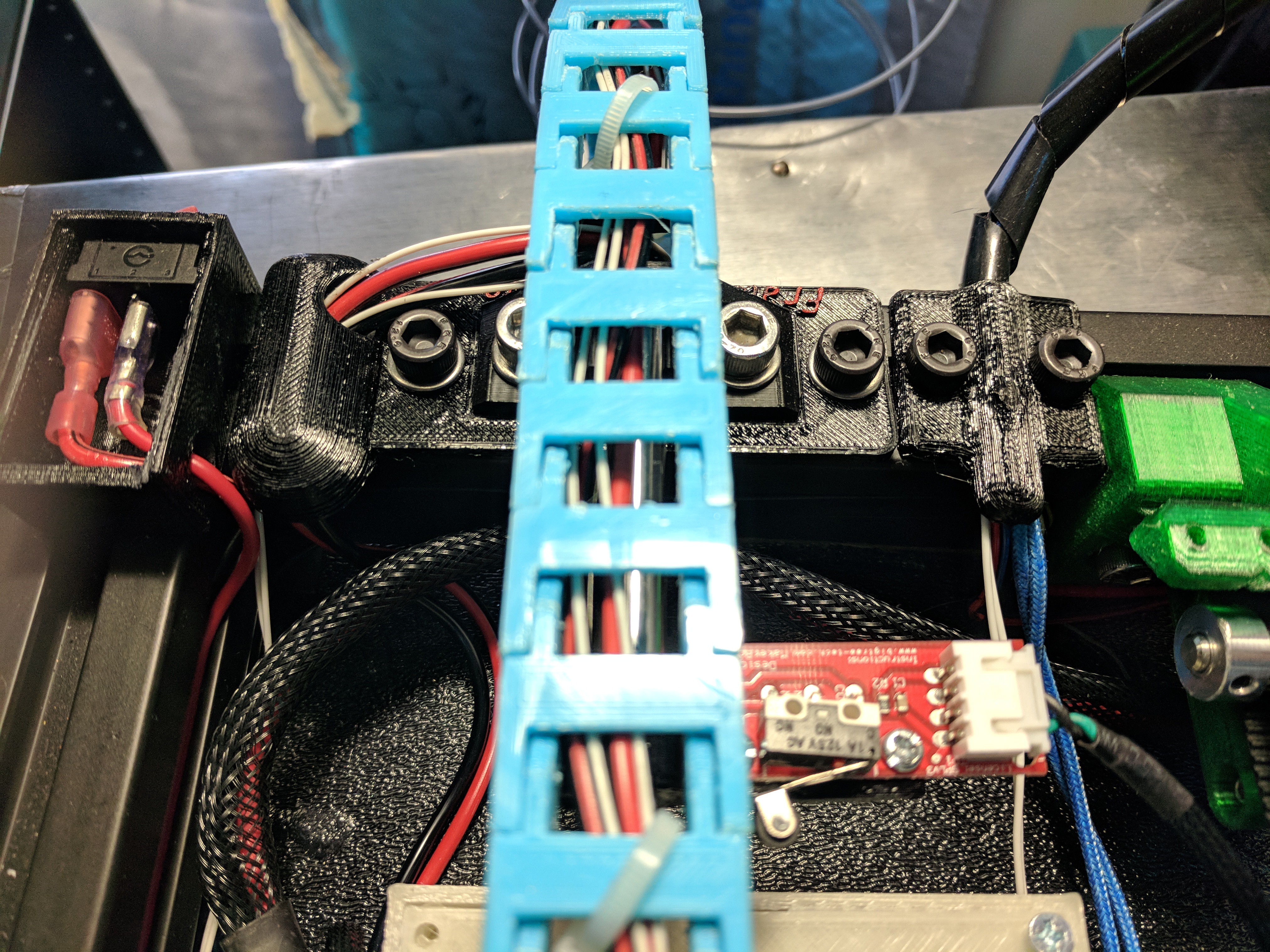
Next up was the wires for the Hotend assembly
and printed
At this point, I should probably re-do those mounts into a single mount...but haven't yet
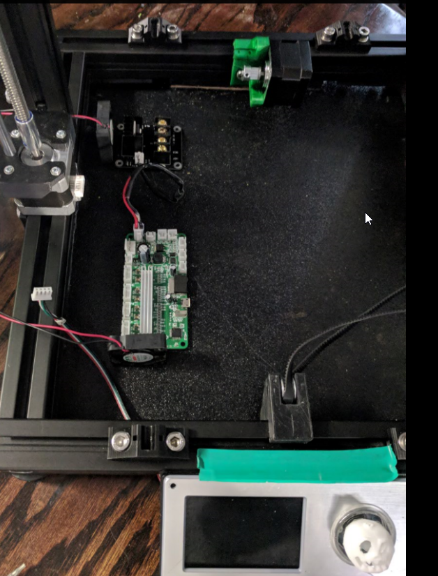
I didnt like the fact that after some time printing this way, the mosfet along with the controller were exposed & prone to me dropping crap on them. like binder clips...or conductive filament...so grabbed a Mosfet case off thingverse printed it, & then started working on a top cover w/fan for my controller
I imported a picture of the controller someone from the FB group did on the wiring, & built my sketch off that.
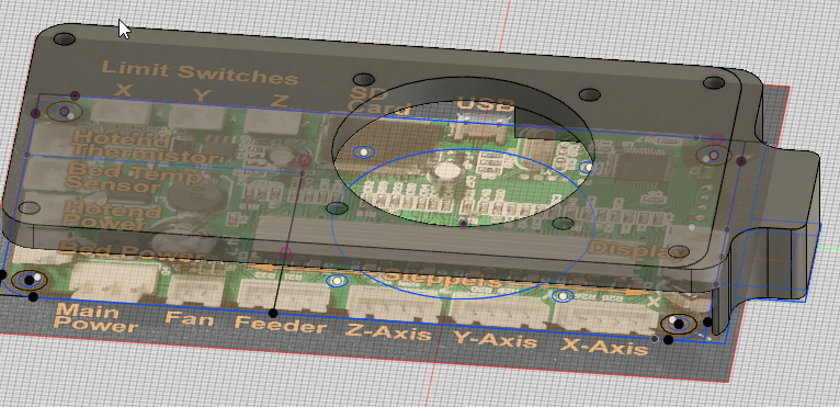
and printed
I added a piece of silicone between my bed & carriage to trap the heat a bit
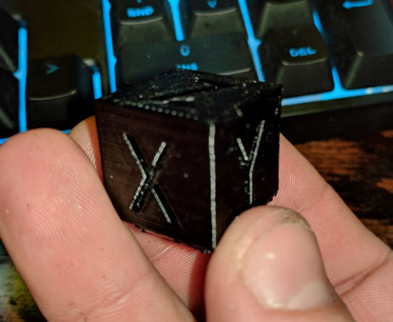
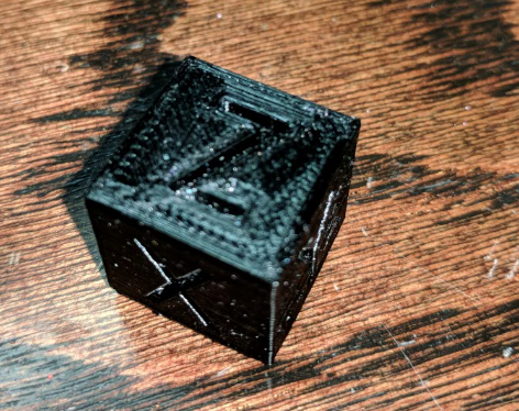
Ran a quick test print at 80mms, 20x20 cube damn near spot on , I did have to run through some calibration to get everything right after this, but it initially printed like -/+.2-5
All wires routed in the frame for the most part, Raspberry Pi Zero W is/was going to be mounted inside, However I am going to pull my pi 3 off my Flashforge-CP put it in this printer, & put the Pi Zero in the Flashforge. The reason is, the FFCP uses sailfish not native Gcode, & I have to run the GPX plugin to be able to print from octoprint. However I print x3g directly from the SD via GPX / octoprint so that I can get time lapse, thus I don't need the GPX plugin to convert Gcode to x3g. the Pi zero can handle this with no issue. However it chokes a bit if trying to print from the Pi's SD card, & run the web browser for octoprint & run the time-lapse; the pi3 is much more capable for this, thus why its going in this "Select Max"
Well that is it for right now. I know I am forgetting a lot of stuff.
some things that come to mind that I will add are:
Switching the mini to use lead screws vs its stock screw.
If anyone has any questions, or comments, please let me know.
Also disclaimer>
I am not an electrical engineer, & only have a very basic knowledge of circuits/electronics. I have no formal training in this & I am self taught. I take no responsibility if you perform any of the above & it results in anything negative. this is just a documentation of my process.
I have been following the Dev of Marlin on Git, & recently Marlin 2.0 has had some PR's for the Minis controller as well as the LCD controller. I hope at some point to be able to flash native marlin to the board so that I can take advantage of some of the newer features that the minis controller is missing. however likely as time goes on I am sure I will end up replacing the minis main controller with something better, but keep the LCD. the new PR for the LCD basically accepts the minis LCD commands/& formats them into Gcode for the controller to interpret (I am grossly oversimplifying here) So a smoothie, or the rambo may be in my future as I like to run some silent step sticks & use the other Prusa features like print resume, "fast" mode, etc
Also bearings in X & Y are Igus RJ4Jp's, Z are the longer lm8u's
I have over 200hrs now on the printer in this configuration with no ill effects. I even ran a 52 hr print that went fine until I ran outta filament while I was at work (52 hrs is an estimate, total print time was 59 est in simplfy3d, at 8 am when I checked on it & left for work, it was on hour 52...I should have checked that It had enough filament left but didnt....hindsight is amazing..)