 Luc
LucFor the visual interface of the compass, I am planning on using 8 LEDs laid out in a ring. Since I'm planning on using an ATTiny85 at this point, I would only have 4 pins for driving the LEDs (with 2 already used for the I2C connection to the magnetic field sensor). Thus I did some experimenting with different ways to drive the LEDs without any extra components.
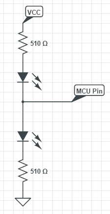
I tried out charlieplexing first, but for only turning on a single LED at a time, the flicker was quite noticeable. Thus I tried out a different method, with only 2 LEDs / pin, in the following configuration:
So I soldered up a ring of LEDs and hooked everything up to a 5V trinket (from Adafruit) that I had laying around. However, I ended up having to use 3.3V for Vcc on the LEDs, since the resistors were not large enough to prevent both LEDs from turning on with 5V as Vcc. On the final PCB, I'll make sure that I choose high enough resistor values, but since this was just meant as a demo, the work around will do. Once I had everything hooked up, I noticed there was another issue: one of the LEDs would remain on even when coded to be turned off.
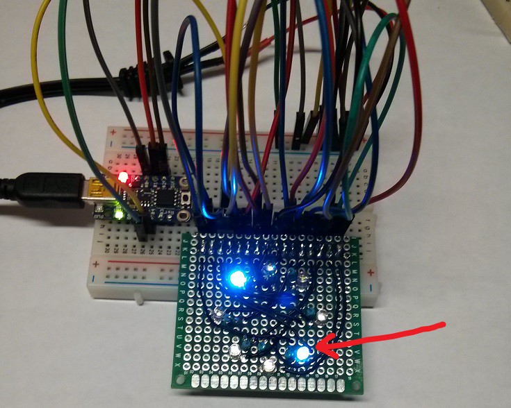
I made sure all the connections were good on the breadboard and the PCB, and that none of the wires were loose/shorting, but the same LED kept giving me issues. I tried switching the pins around, and apparently pins 3 and 4 of the trinket I am using have issues with Hi-Z mode (input mode), since none of the other pins had the same problem on any of the other LEDs. I'm not sure if there is just some capacitive coupling on pins 3/4 from somewhere else on the board or if there was some interference (although turning off the fluorescent lights didn't help at all), but I ended up just putting a 1 kOhm pull down resistor on pin 4 of the microcontroller (show below).
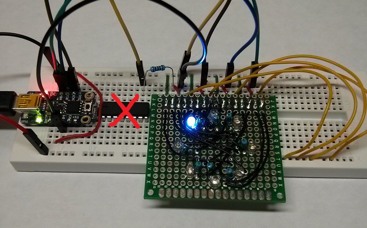
Doing so got rid of the problem, so I may have to do something similar on the final board, or even use a shift register or decoder chip for driving the LEDs. I would like to avoid doing that, as extra chips would require more power, take up more space, and increase the final cost. Hopefully getting rid of the reset pin (using it as I/O) won't cause any problems (fingers crossed that I can get the firmware right on the first go) but we'll see what happens.
Discussions
Become a Hackaday.io Member
Create an account to leave a comment. Already have an account? Log In.