 johnowhitaker
I finally got the ATtiny85 code behaving as I want. It simultaneously sends out an ultrasound beep and flashes an LED. I can now start writing code to detect these and estimate distance. The code uses the internal timer1 to do PWM, generating the required frequency without using up CPU resources. This is vital as it will need to do other things. I also have interrupt code for when a button is pressed and some other fluff, but for now this is all I need to test everything. Here is the code:
#include <avr/io.h>
#include <util/delay.h>
#include <avr/interrupt.h>


// write digital high or low to pin <pn> on port <prt> - good for arduino converts
#define DIGIWRITE_H(prt, pn) prt |= (1<<pn)
#define DIGIWRITE_L(prt, pn) prt &= ~(1<<pn)


void initTimer(){
  //TCCR1 = _BV (CS10);       // for no prescaling
  TCCR1 |= (1 << CS10);       // PCK/2
  //TCCR1 |= (1 << CS11);      // uncomment the rest of these to lower the frequency to ~1Hz
  //TCCR1 |= (1 << CS12);      // look at ATtiny85 datasheet to see which bits scale the clock of timer 1 by what amount
  //TCCR1 |= (1 << CS13);
  GTCCR = _BV (COM1B1) | _BV (PWM1B);  //  clear OC1B on compare, we'll be doing PWM with the output directly toggling PB4 (OC1B)
  GTCCR = _BV (COM1B1) | _BV (PWM1B);  //  clear OC1B on compare, we'll be doing PWM with the output directly toggling PB4 (OC1B)
  OCR1B = 80;                   // duty cycle (50%) = freq/2
  OCR1C = 160;                  // frequency (lower = higher frequency)
}  // end of setup


void main() {
    initTimer();
    //DDRB is the data direction register for port B - the io pins on the ATtiny85 are all in port B.
    //Each bit refers to one pin. 0 means input, 1 means output.
    DDRB = 0b00001000; //pin PB3 to output and PB4 + the rest to input for now(pins 2 and 3 on DIP ATtiny85)
    for(;;){
        DIGIWRITE_H(PORTB, PB3); //turn LED on
        DDRB = 0b00011000; //allow output on the speaker pin (PB4). This saves having to stop and restart the timer each time.
        _delay_ms(500);
        DIGIWRITE_L(PORTB, PB3); //turn LED off
        DDRB = 0b00001000; //turn speaker off
        _delay_ms(500);

    }
}
I program the chip with a bus pirate as detailed in a previous log, and I can then easily test it by turning on power from the bus pirate from a serial console. The uses of that tool continue to amaze :)
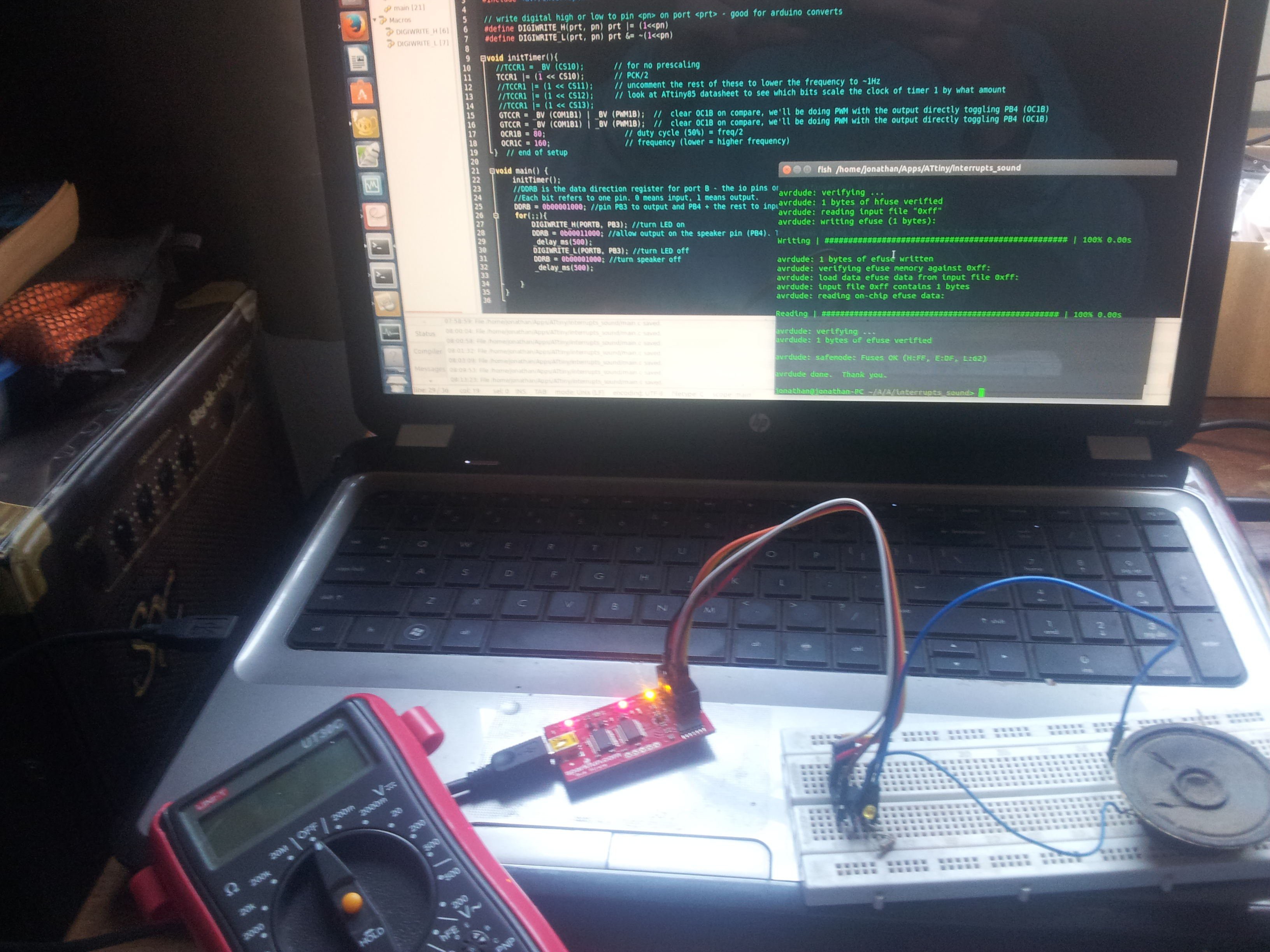
Next in the TODO list is to hook up a mic + preamp to the teensy and see if we can detect sound...
Discussions
Become a Hackaday.io Member
Create an account to leave a comment. Already have an account? Log In.