 Jeremy g.
It's exiting when something works!
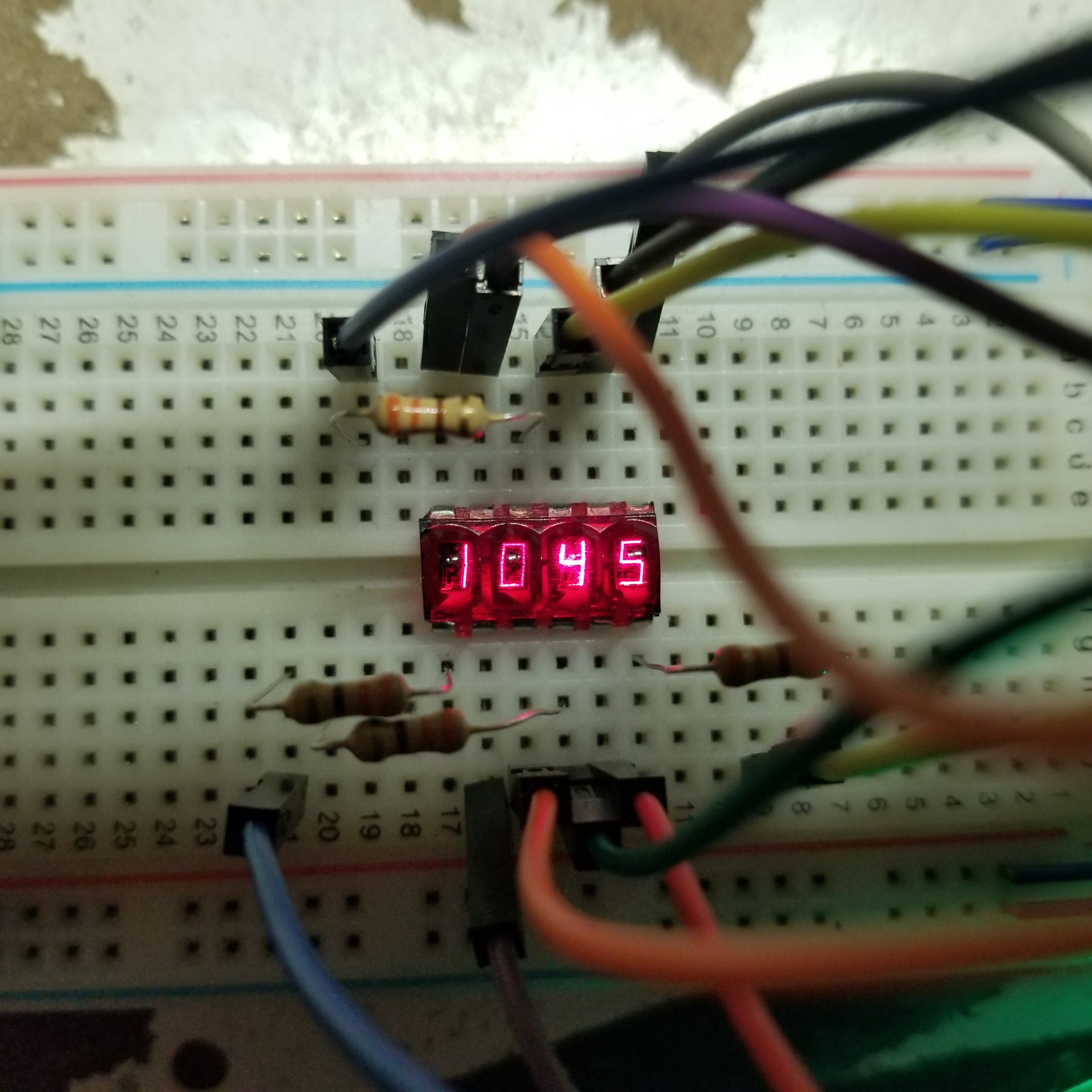
We have a clock! turned out I was using the wrong address for the RTC.... have to remember its 0xD0 not 0x68.... coding all day at work then doing so at home... you miss a lot of little things..
This clock turned out much, much easier than my micro numitron clock project. Code wise, I ended up using the i2cMaster library from Peter Fleury i2cmaster library, its a bit banged assembly library that just works and its amazing!
Ok so now to the rastering or how we control the 74HC595's
The 595's in this setup are cascaded together, they both share the same CLOCK andLATCH pins, the first 595 gets the DATA pin from witch we feed it a 12 bit binary number, the first 595 also feeds the rest of the bits to the other 595 via Q7` (that's prime). The 595 can only hold 8 bits of data, so when this overflows ( you push 9 bits) if available it will push the 1st bit your MSB to the Q7` pin witch is then connected to DATA pin of the second 595 and so on and so on.
Here's how getting the digits displayed it structured.
[digit symbol] [display digit]
[8 bits ] [ 4 bits ] = total 12 bits.
this is all read out LSB first so the Anode positions go out first ie 0b1111... 0b1110.. etc since the Digits bits are Anodes we need to sink current so in order to turn a digit off, we simply write a 1 in its position.
looking at the photo ^, we see, as I have have arranged them in code. Pos 3, 2, 1, 0. so
Pos 3 = 0b0111
Pos 2 = 0b1011
Pos 1 = 0b1101
Pos 0 = 0b1110
so how do we raster them, if we were to send say all digits like so 0b0000, then the symbol that got sent out would display across all of the digits.. we don't want that. So our goal is to light each digit space one by one at a super fast pace, so it looks like they are all on at the same time.
so for instance.
while(1){
    send(0b0111);
    send(0b1011);
    send(0b1101);
    send(0b1110);
}
Really all we are doing is just sending the bits we want really fast to the 595's. You can see this effect if you take your phone camera and point it at a screen or clock (digital) you will see the digits flicker, this is the rastering effect. the camera is fast enough that it can see the flicker where as usually past 60-120 hertz the human eye just sees a constant image. pretty cool.
I will leave the test code in the main program on the repo in case anyone is interested in looking at how I tested things. a quick note. For those of you not familiar with C
#if 0
    foo
#else
    bar
#endif
This statement will only run bar, unless #if is 1. this is a good way to comment out code for future testing or use, the compiler will not compile anything in the #if 0 statement into your final output. this can save lots of space if perhaps you have lots of debugging code in place.
Next up is a simple interface to set time, display seconds. etc. I need to setup an interrupt for the output of the DS1307, so we can flash one of the DP lights to indicate seconds.
Until next time :)
Discussions
Become a Hackaday.io Member
Create an account to leave a comment. Already have an account? Log In.