This is a super simple schematic, even though it may look chaotic at first glance.
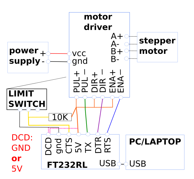
Notice that I have not connected the power supply ground to the FT232RL ground. Only when it absolutely does not work without, should you do this, really. Connecting them may actually cause problems, especially if it's a switching power supply that is a bit 'nasty'. All the motor driver control inputs are optically shielded anyway, which is good.
First of all, we require a power supply. The motor driver I used, the TB6600 (https://www.makerguides.com/wp-content/uploads/2019/10/TB6600-Manual.pdf) requires a DC voltage between 9-42 VDC. The prusa motors that I got from Ebay did not specify what current they wanted, but comparable ones from Amazon require 1.5 A. https://www.amazon.co.uk/gp/product/B01DVD87Q6
Remember to configure the motor driver current to 1.5A. This is described in the manual, link above. Configure the microstep to "1", which means "let's not bother with microstepping for this".
So let's use 1.5 per stepper motor. Typically, the higher the supply voltage for the power supply, the happier the steppers are. Because we have two stepper motors in our 'mirror system', we need 3A in total.
It's super easy to find 24V switching power supplies, for instance:
https://www.amazon.co.uk/Vbestlife-100-240V-Converter-Switching-Transformers-default/dp/B07KPCCQBS, which is a 24V, 4A power supply. It's always better to have a power supply which can supply more current than required, and these types of switching power supplies come with built-in current limit detection. If anything goes wrong, it won't (should not!) self destruct. And touching 24V is not going to kill you.
For the motor driver I'm using the TB6600, as already mentioned. On its right, it has 4 outputs: A+/- and B+/-. A and B are the two windings of the prusa style actuators; I got these from Amazon:
https://www.amazon.co.uk/gp/product/B01DVD87Q6
If you don't know which of its 4 wires belong to output A or B, just use a multimeter in the continuity or 'beep' setting, and find the two wires that 'beep' when you test them. Call them winding A or B, it doesn't matter, unless you're building multiple mirrors, in that cause you'd like to have the correct pair, otherwise the different mirror systems will react differently to the control signals (direction of turning may change). Also test that the remaining two wires 'beep', and connect them to the motor driver. The motor driver has to be close to the motor, because it doesn't really like to drive long leads. It may work if the pulses are quite long, such as 1200 baud or so, but I digress.
So connect the wires that you call A to the output A and the wires B to the output B. Again, it doesn't matter which way around they go, it only matters if you build multiple systems and you want all mirrors to behave the same.
Because in the Labview program, you can easily change the DIR signal (direction).
Okay, so we come to the FT232RL converter. There are several signals:
TX: to send the pulses
5V (orange) : this output supplies 5V to the TB6600.
TX to PUL (green): this provides the pulses, as discussed in an earlier project log.
DTR to DIR- (purple): this provides the direction signal.
CTS to ENA- (blue): this provides the "enable" signal. If this signal is low, then the motor driver is enabled. This signal needs to be high when the mirror is not adjusted at that time, otherwise the motor driver will continuously use power. This is not going to destroy anything, but wastes energy, and that is more or less what this project is trying to prevent, right?
DCD (pink dotted): connect to 5V or gnd NOT BOTH!! Why this signal? Remember, we're going to have two motors in this system, and it would be nice to be able to identify them easily, and not get the axes switched accidentally, sending the mirror in the wrong direction. So for one of the axes, this signal has to be high, and for the other axis, low. This signal can then be read in Labview.
RTS (yellow): When this signal is high, the limit switch is not engaged, and when this signal is low, it is engaged. The signal should always be high because it is pulled up by a 10K resistor, and the switch merely shorts it to ground. The 10K resistor then limits the current to a safe level (5V/10K = 0.5 mA).
Note: due to historical reasons, a "high" signal, or "engaged", or as Labview calls it "asserted" may be high or low. In other words: experimentally it needs to be verified whether asserted is 5V or 0V, and unasserted the other way around.
That is the entire schematic! Well, half of it of course, because the same system needs to be duplicated for the other axis.
summary of list of electronic components:
- power supply: https://www.amazon.co.uk/Vbestlife-100-240V-Converter-Switching-Transformers-default/dp/B07KPCCQBS
- plug for power supply connector: https://www.amazon.co.uk/EFISH-Connector-Terminal-Adaptors-Security/dp/B07RHM5KCW
- a long thick wire pair to connect the power supply to your mirror system outside: https://www.amazon.co.uk/MANAX-speaker-cable-mm%C2%B2-black-Red/dp/B01DDJX920
- 8 core shielded cable for the signals, such as cat7 cable: https://www.amazon.co.uk/100-0M-Cat-7A-Ethernet-Network-Halogen/dp/B0749NQRK3 . The shield has to be connected to ground on the power supply side.
- some 8 pin connectors: https://www.amazon.co.uk/Thread-Female-Aviation-Connector-Ltsstoreuk-Silver/dp/B07BFDFJ1T
- actuator: https://www.amazon.co.uk/gp/product/B01DVD87Q6
- motor driver: https://www.amazon.co.uk/TB6600-Stepper-Driver-Controller-Segments/dp/B07FXH9TYM
- FT232RL: https://www.amazon.co.uk/Yizhet-FT232RL-Converter-Adapter-Raspberry/dp/B07R17BMTL
- 10K resistor: https://www.amazon.co.uk/POPESQ%C2%AE-Resistor-Suitable-0-25W-A2428/dp/B07KX4YVY3
You probably need some wires https://www.amazon.co.uk/TUOFENG-Wire-Solid-Different-Colored-spools/dp/B07V5FVSYL
and a soldering iron and some tools: https://www.amazon.co.uk/Soldering-Multimeter-NO-Soldering-Welding-Cutter/dp/B07F2XNTWV
- and a windows PC or Laptop.
I've just given you some quick examples. If you do a bit of sleuthing, you will probably find cheaper components, which may do the job just fine.
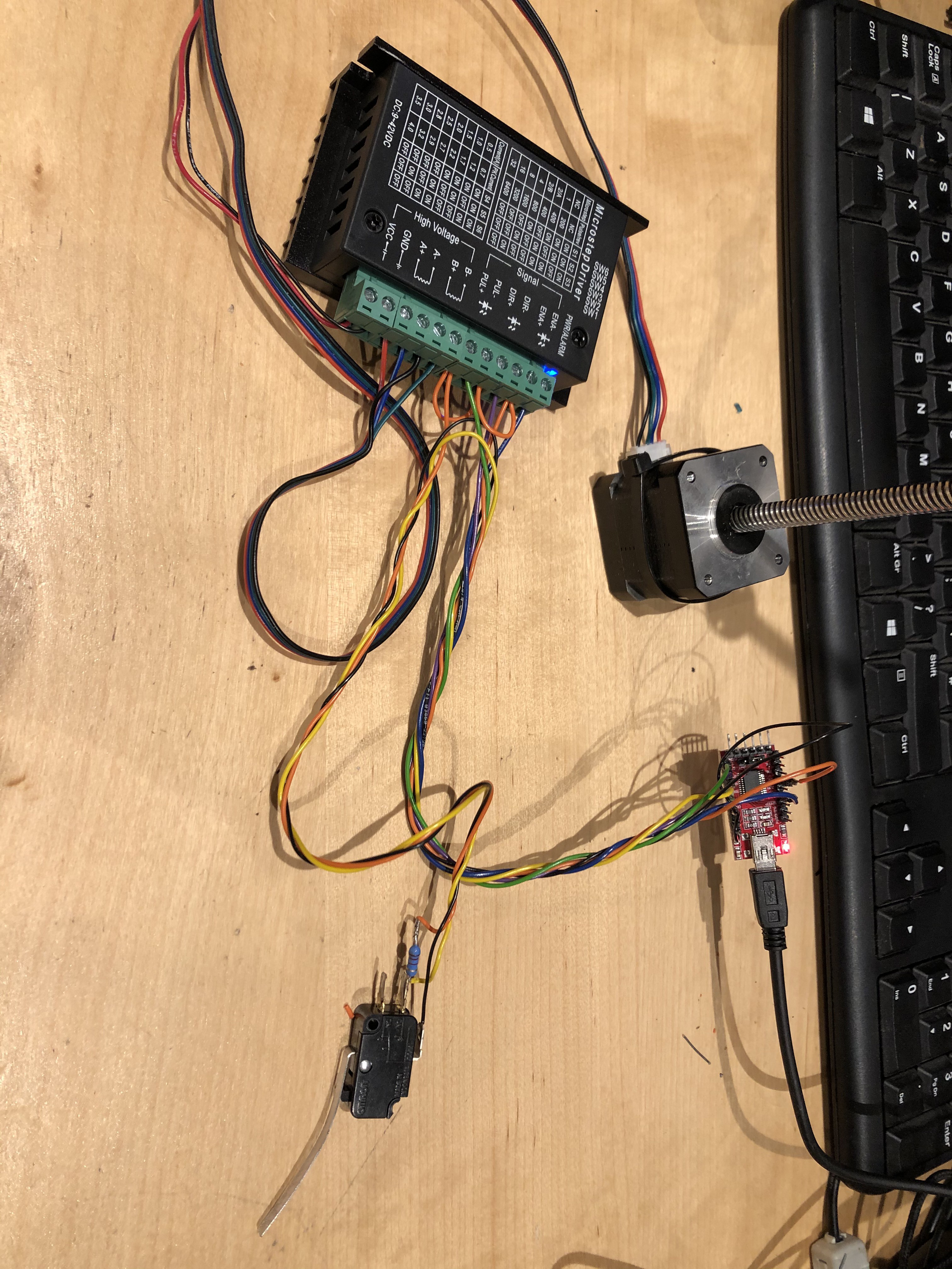
Here's a high-def photo of the setup. With some care you can make out the connections. But really, just look at the schematic, that is what it is for.
Discussions
Become a Hackaday.io Member
Create an account to leave a comment. Already have an account? Log In.