 Alex
AlexIntroduction / Motivation
My experience with the ESP modules started with the ESP-01 module. First only with the simple AT-Commands over the serial interface. Later, when it was available, I started to use the Arduino IDE for ESP8266. For the ESP-01 I had developed an small #ESP-01 Breakout Board.
The board was on homebrew PCB and only uses the ESP-01. So the PCB and soldering was not good nor professional looking this way, but it works. But the IOs of the ESP-01 were quite limited. So I came up to design I new PCB for the "bigger" modules (they use all the same chip).
Some advantages of the modules with a custom PCB :
- easy and ready to use
- as simple as an Arduino, but:
- faster CPU
- wifi!
- more memory - not much more expensive
Features
(I only writing here about the newer rev2 - rev1 was similar but in some aspects different. It has also fewer features)
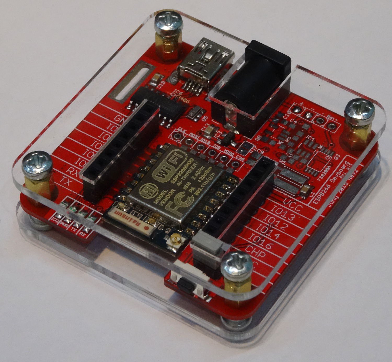
Based on my experiments with my ESP-01 breakout board this board has the following features:
- Pads for ESP-12 , ESP12E, ESP-07 and ESP-01 Modules
- on Board power supply from:
- USB (MINI)
- external power source (2,1mm power jack and 2,54 mm pin header)
- lipo battery (for off-grid operation)
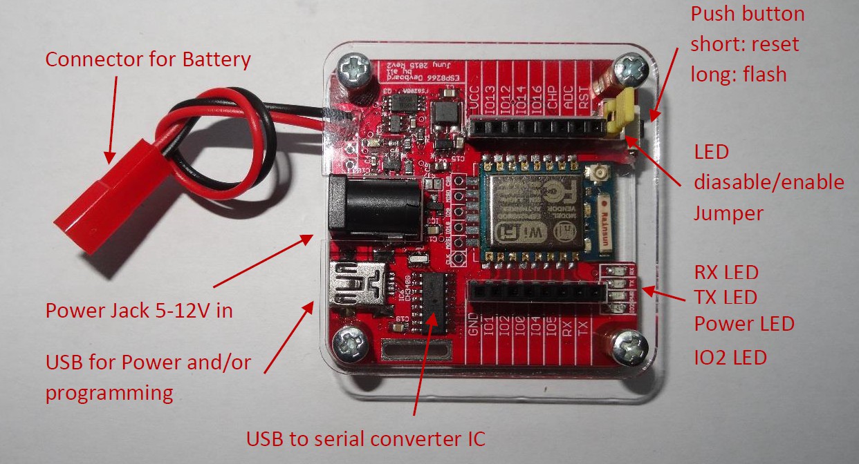
- on board programming via USB to serial converter
- Headers for IOs
- rest / programming switch
- User LEDs: RX, TX, Power and GPIO2 LEdis available on the board
RX, TX, and Power LEDs kan be en/disabled via a Jumper to save power - Jumper to connect IO16 and reset (need for deepsleep?!)
New with rev 2.2
- optional compatibility to the NodeMCU boards
- mini OR micro USB
- polarity of power jack changed. now the centre pin is positive
- nice three row pin headers for direct servo connection
- now also FTDI-pinheader possible to connect external USB-Sertial board
Power supply
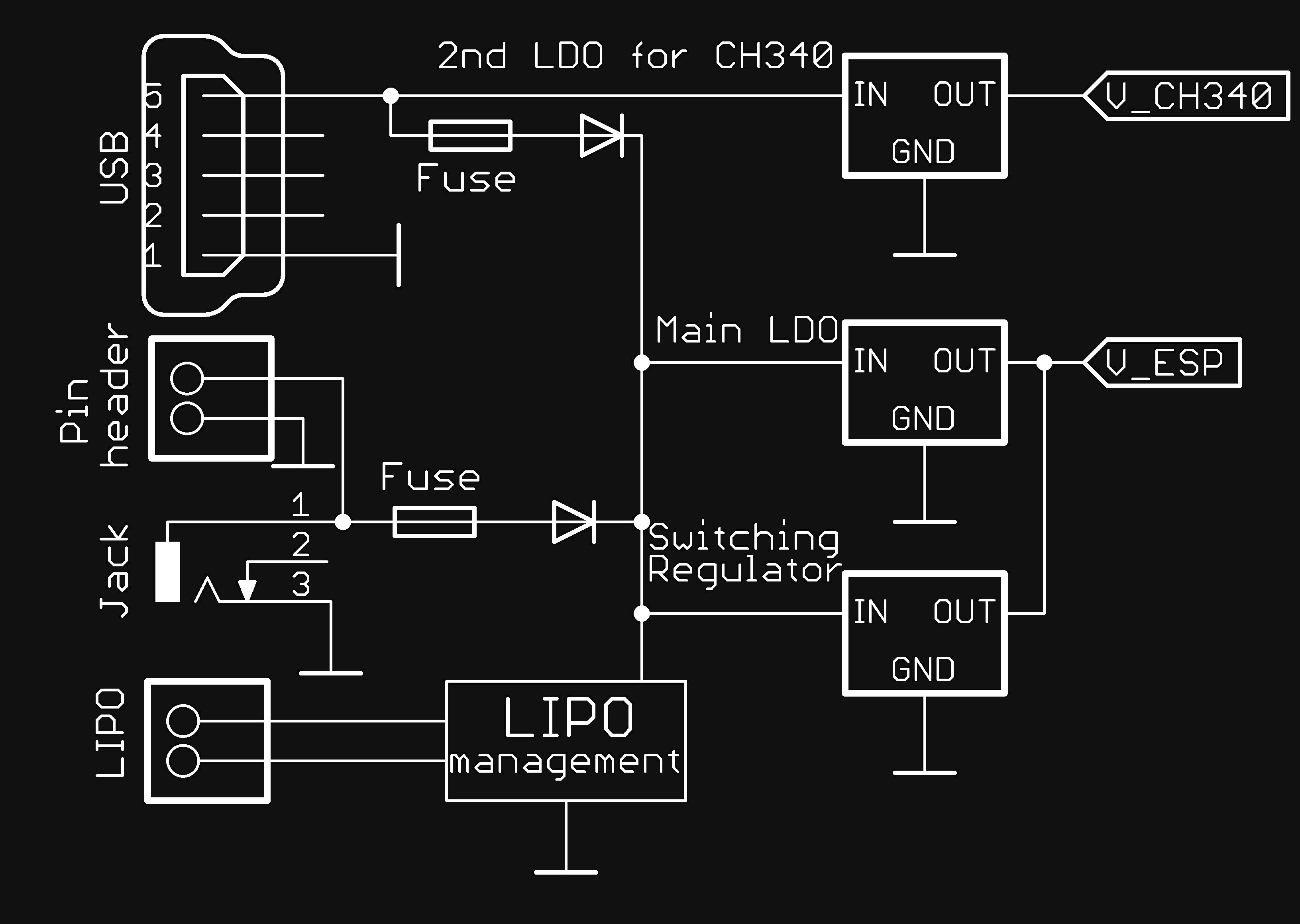
I wanted to make a very flexible power supply. Beside there different power sources, you can assemble two different regulator settings. As power source the USB-Power, an external DC-Voltage or a lipo battery can be used.
When connecting the Device via USB to a PC USB-Power can be used. You can also connect normal power to the Device via the USB connector.
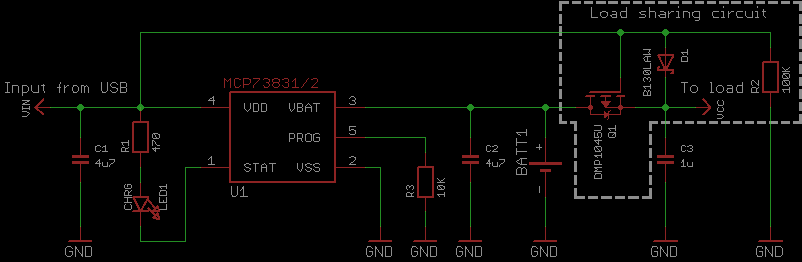
For the lipo Battery there is some charge and protection circuit prepared on the PCB. For charging a MCP73831 is used. As lipo Protection a used a DW01-P. In rev2 there is now also a load sharing circuit (source) available. The battery must me connected to 100mil pin header on the PCB.
The third way to Power this device is the 2,1 mm power jack. The center is positive. (There is is mistake on Revision 2.1 or earlier: The Center Pin is negativ!!!) This is the same Jack used in most Arduinos. Beside the Power Jack there is alternative a 100mil pin header.
The power source is selected automatically via schottky diodes.
For the main voltage regulator there are two options:
1. Standard LDO (AMS1117-3.3 easy to use totally common regulator datasheet)
2. Switch mode regulator (LM3671MF-3.3 much more efficient datasheet)
There are SMD jumper onboard to select one of them. Additional there is another small LDO. It can be used optional to power only the USB to serial converter. But the USB to serial converter can be also powerd from the main voltage regulator.
Adjusting the battery charging current
To set or adjust the charging current to different batteries you must select an suitable value for R8. The equation for the current is (according to the data sheet):The units are kOhms for R8 and mA for the calculated current. [MCP73831/2 data sheet p. 15]
Case
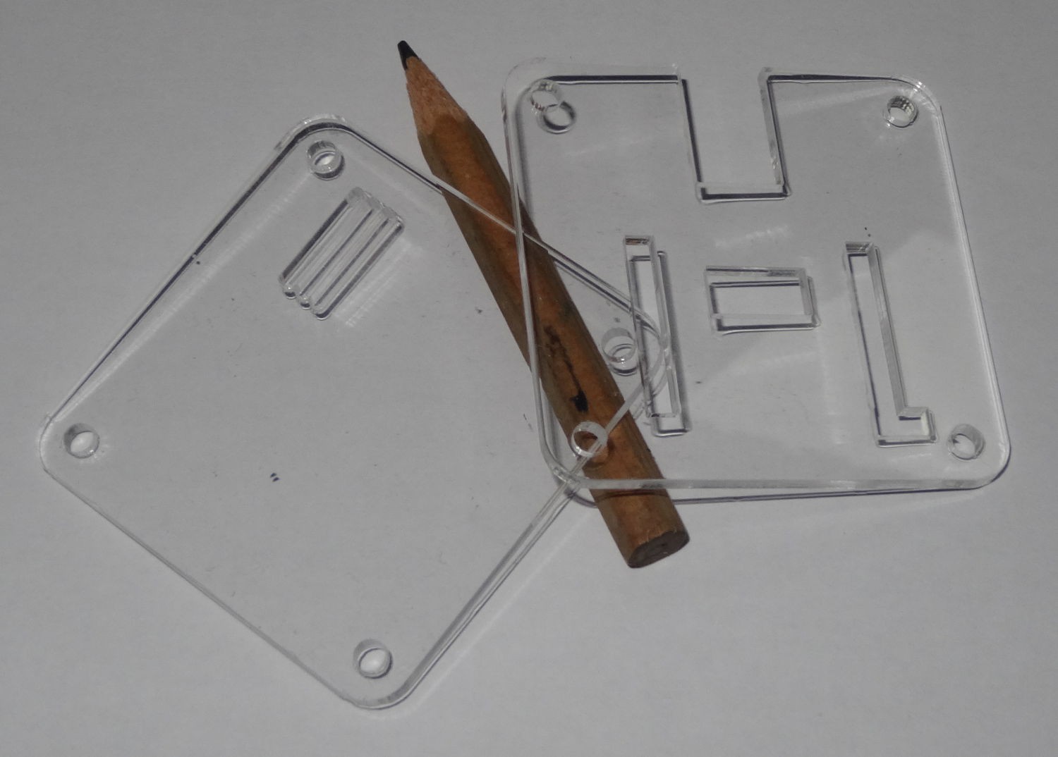
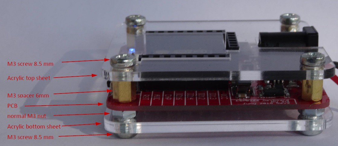
While the first revision has no case, only screw holes to mount the PCB somewhere (and these screw holes were to small) . I decided to make a case for the second revision. First I was thinking about a off the shelf case like this. But This was to small and I could not find one with is big enough but not to big. On the other hand most cases are non transparent and you will hide all your work. So I came up with the "Sick of Beige Cases" . This is nothing more than two transparent acrylic sheets screwed on both sides of your PCB. So I designed nice custom acrylic sheets for my modules. These do have cut outs for the various connectors on the Top.
Programming
The ESP module is programmed via the serial interface. Therefore I used an USB to serial converter to connect it to modern PCs. I used an CH340G. This is a very cheap Chinese IC. I could have also used the more common FTDI FT232 here, but they are expensive and the manufacturer had done some strange things in the past.
Beside the interface. You have to pull down IO0 to get in the programming mode. I used some circuit from baoshi to archive this through long pushing the reset switch. See his project for further Information. Once in program mode you can upload your sketch via the Arduino IDE similar to an normal Arduino.
Future
Ideas for future revisions ( just as a note to myself)
- Version without lipo management and all component on top side
- use a bigger and easier to solder crystal
- onboard i2c fuel gauge
Credits and Sources
Thank you all who have pointed me to these improvements
Named
baoshi (link) - similar project here on hackady io were I got the rest/programm circuit from
Zak Kemble (link)- good articel about the MCP73831/2 and source of load sharing circuit I will use in Rev2.
davedarko his project was inspired by mine, but he had some great additional ideas (like the notch under the antenna) which I will use in Rev2
Hari Wiguna (link) - Arduino IDE for ESP8266 Quickstart Guide -as further reading how to use the ESP module with the Arduino IDE
forgotten someone?
Unnamed
Further on I will thanks everyone who help me with advice or testing during the development. I hope they and additional people perhaps will support me further.
Errata
All revision
- powering the Ch340 from the main 3.3 LDO do not work. Please power it from the 5V VUSB (take care of the resistor divider on TX) or use the second small sot-23 regulator (recommended workaround). I will try to fix this.
Rev1
- Labeling of GPIO4 and 5 are switched
- RX LED is RX of PC not of the ESP (ESP: TX)
- TX LED is TX of PC not of the EPS (ESP: RX)
Rev2
- Labelling on top side of the battery connection is wrong! Connect Battery as written on bottom side
- missing wire on bottom side (see picture below). If not fiexed you can not use the power, RX and TX LED. See also this project log!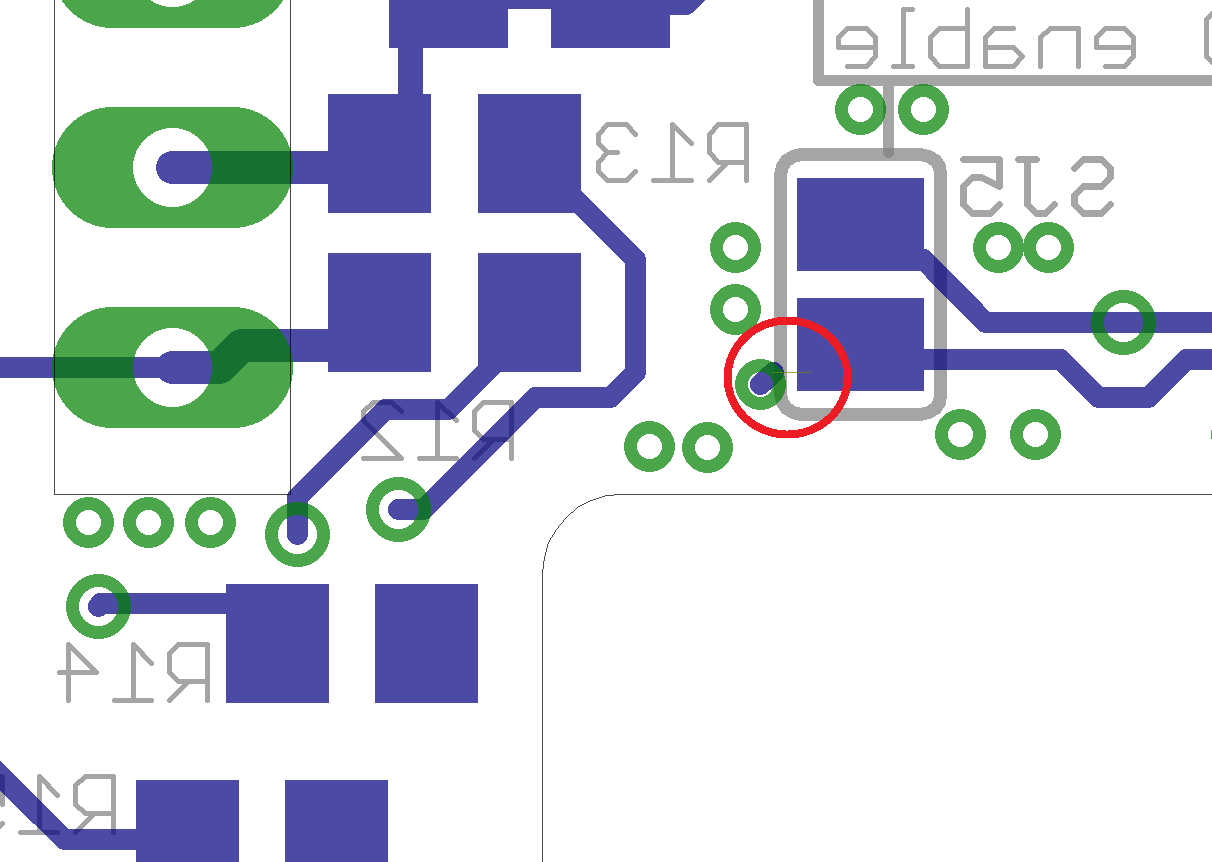
- The center pin of the Power Jack is NOT positive its negative. So the opposite of the Arduino UNO Power Jack.
Rev2.1
- The center pin of the Power Jack is still NOT positive its negative. So the opposite of the Arduino UNO Power Jack. Will fix that in next revision.
some Endnote: As you could have noticed English is not not my native language. I try to do my best to write as good as I can. So if you find any mistakes or have ideas to say something more clear, please send me a message!