Hello Hackaday.com readers! Not sure who submitted my project (if anyone) but I am excited to see it there nonetheless!
When I last checked in, I was working on a solution for the graphical display of satellite position. I'd decided on the Bulgarian Pravetz Apple II clone as a suitable platform, and had been working away on some 6502 assembly code to draw the map and satellite position. I also said, "something-something hook Bulgarian Apple II clone up to transputers" and proceeded to ramble on about other stuff.
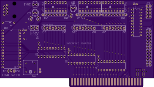
At some point I did mention that a design for the link adapter interface would be forthcoming. Let it not be said that I don't deliver. I give you, the Keplermatik Interface Adapter:
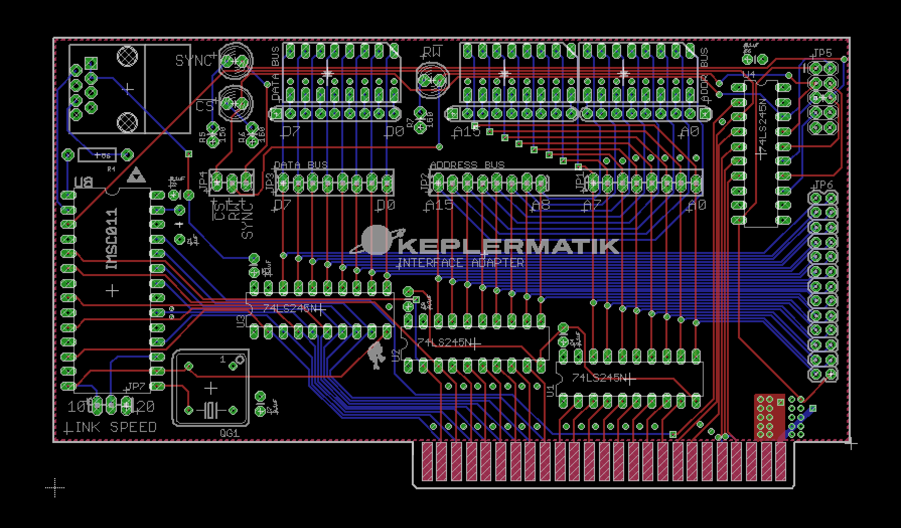
Yep. It's a circuit.
First of all, the more astute observers among you will notice that there's a bit more going on with this board than a simple link interface. There are a few buffer chips, some LED arrays... Oh wait, it's...
BLINKENLIGHTS!
As I was drawing up this circuit, I started thinking about how handy it'd be to break out the bus signals for debugging purposes. That led to thinking about how old machines showed all that on the front panel, and at that point it pretty much came a foregone conclusion that Keplermatik was getting some sweet address and data bus activity indicators, a.k.a. Blinkenlights. For early development, there are some onboard LEDs that will provide a sweet disco scene under the hood, but more importantly there are some double-row headers toward the rear of the card that will connect via ribbon cable to a DB25 and DB9 on the back side of the machine. Later, the Keplermatik console will have some nice big blinkenlights that connect to those ports.
So enough about lights, what about the super-awesome INMOS transputer link?

As mentioned in an earlier post, this board is designed around an IMSC011 link adapter, pictured above. This is the chip that does the important work of allowing the Apple II to talk to those wily transputers.
When in its Bus Interface mode, it's silly how easy the IMSC011 is to interface to the Apple II. The 6502 uses Memory Mapped I/O, and the Apple II has some special address decoding going on that allows a peripheral slot to know when it's being talked to.
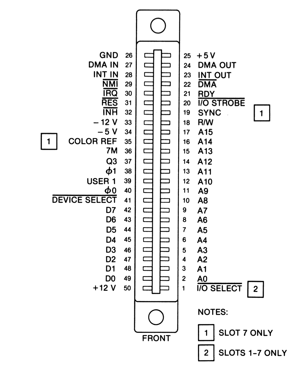
As seen in the above connector pinout diagram, Pin 41 of the bus is called "Device Select", and the decoding circuitry takes it low when any memory in the range $C0x0 to $C0xF is accessed (where x is the slot number + 8). This can conveniently be connected to the IMSC011's Chip Select (CS) line, which enables the link adapter when taken low. This signal, combined with the RW (read/write) line and two address lines, is basically all that's needed outside of the data bus to send and receive data through the link adapter.
About those two address lines. The IMSC011 has a set of registers that can be read and written to determine link status. These registers are selected through various combinations of the RS0 and RS1 Register Select lines, and connecting these to the lowest bits of the Apple II address bus essentially maps those registers into the Apple II's address space. How, you ask?
Remember how that device select line goes low when memory in a certain range is accessed? That's because the address decoding circuitry ignores the 4 lowest bits of the address, leaving them available for the device to do stuff with. So, if we connect the 2 lowest bits of the address bus (represented by the A0 and A1 address lines) to the IMSC011, then when the Apple II bus selects those lines in the process of accessing its memory the registers will appear on the data bus.
Another side effect is that since we're ignoring A3 and A4 (and the Apple II isn't decoding them to select our device), then the registers actually repeat throughout that portion of the memory space! For example, the register at $C0x0 will also appear at $C0x4, $C0x8, and $C0xC.
One thing about hardware of this vintage, there are no fancy SPI peripheral drivers or anything like that required to interface with it. All you need is to read and write some memory addresses from assembly, BASIC, or whatever. An elegant method, for a more civilized age.
So what else?
Aside from the circuitry just described, there is a 5MHz oscillator to drive the IMSC011, a jumper to select the link speed (10 or 20 Mbps), some miscellaneous caps, and an RJ-45 port for the INMOS link itself.
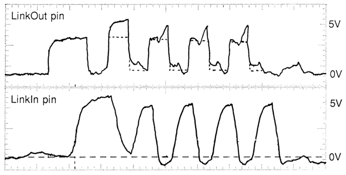
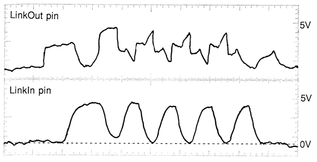
Oh, there is in interesting little detail that I dug up in an INMOS technical note about series termination of the INMOS link. Adding a 56 ohm termination resistor provides proper impedance matching when using twisted pair. The graphs below show the signal with and without series termination.
Well, that pretty much wraps up this installment. I'll leave everyone with this nice rendering of the board that OSHPark spit out when I placed my order. Purple will do for now but I'm thinking that when this all goes together for real, a more era-appropriate color is going to be necessary!
Discussions
Become a Hackaday.io Member
Create an account to leave a comment. Already have an account? Log In.
Just nitpicking - "Soviet Pravetz Apple II clone" - Pravetz was Bulgarian company, actaully https://en.wikipedia.org/wiki/Pravetz_computers
Are you sure? yes | no
Thanks Jaromir, I made the correction. An important distinction, not all countries behind the Iron Curtain were Soviet!
P.S. I just went back to edit the previous post too and it was already correct there, ha. Sorry again for the confusion!
Are you sure? yes | no
that's a beautiful routing job you have done there!
Are you sure? yes | no
Thanks Dave, it's one of my favorite parts of any project. I have high standards when it comes to board aesthetics :)
Are you sure? yes | no