 Capt. Flatus O'Flaherty ☠
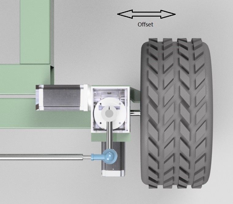
Due to the 'offset' nature of the steering geometry, the steering and the drive motors need to be synchronised so that they don't grind against each other or grind on the ground itself.
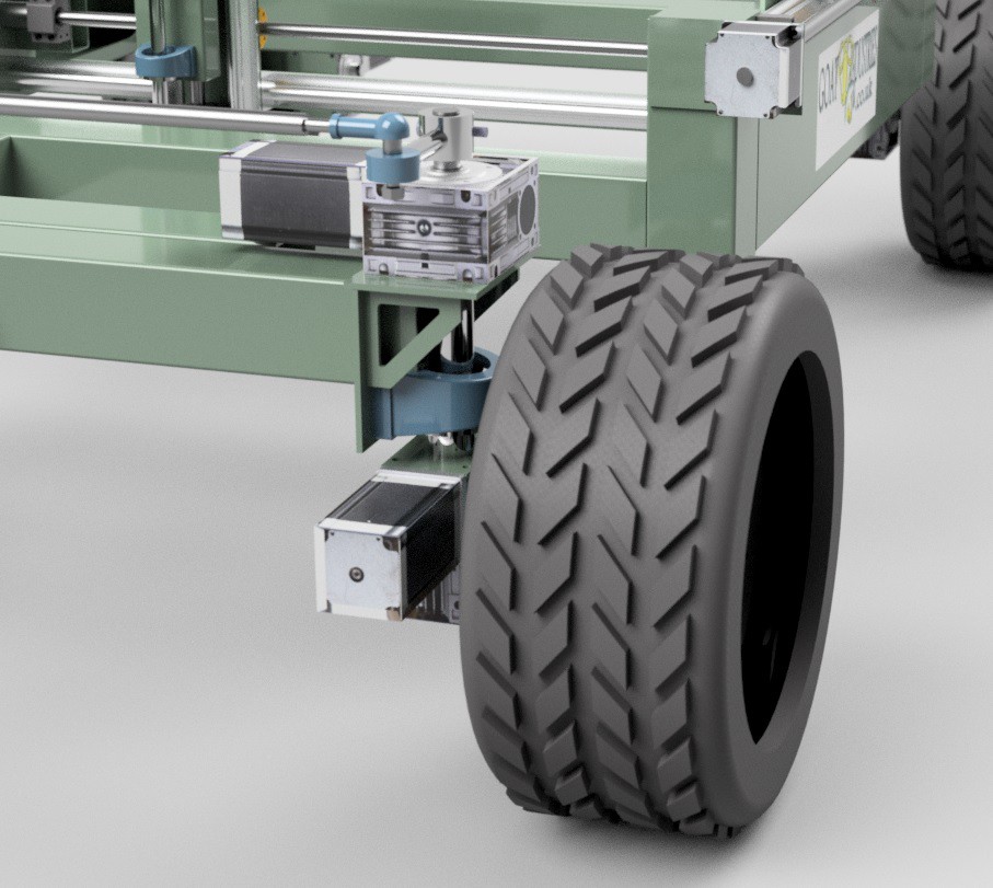
The reason why the steering is offset to start with is that it's much simpler and easier from a mechanical point of view to build it like this and also much cheaper to build. Whilst most cars on the road would have the steering axis much closer to the middle of the wheels, a lot of four wheel drive tractors have the steering offset as in the picture below:
Since we are using electric motors and have a very sophisticated 'position mode' control system with optical encoders, we can create formulae to take account of the non-ideal steering geometry.
It took me many hours to work it out - but eventually I split the problem into two parts - 1. When the machine is stationary and 2. When the machine is moving. But before I go into how the steering works I need to explain a bit about the control code.
The motors themselves are given pulses from the MCU to step forwards and the pulses are generated every time a specified interval passes in the main control loop. This is similar to the familiar 'blink without delay' except that here there are four intervals running synchronously and I use 'micros' instead of 'millis' and the MCU is a super fast TC275 rather than an Uno or Mega. In terms of units, the interval is 'seconds' and speed is 'something per second':
... And in practise this means that we can't just add different intervals together to get speed.
Back to the machine ...... When the steering needs to turn AND when the machine is stationary, the tyres will grind across the floor unless they actually turn very slightly during the steering motion. In theory, the formula should just be based on a simple ratio of the radius of the wheel to the radius of the steering offset, but in practise there are other factors which require the ratio to be adjusted by a factor of 2. Also, when the steering turns in this 'stationary' case, one wheel needs to turn slightly forwards and the other slightly backwards!
In my code, 'intervalThree' gives the right hand motor speed and 'intervalOne' the RH wheel steering speed and the formula for steering when stationary is very simple:
intervalThree = intervalOne * radiusRatio * 2
This formula was tested on the machine and I could see that the torque on the drive motors did not significantly change whilst steering ..... Success!
When the machine is actually moving, the formula is a bit more complex as we need to add speeds together. Essentially, we need to add the speed calculated as above to the speed of the drive motor at any given time, ie wheel speed + steering speed x radius ratios x 2 ..... BUT our units of speed are in 'per second' so we have to invert the speeds first. The actual formula looks something like this:
intervalThree = 1/((1/intervalThree) + (1/(intervalOne * radiusRatio * 2)))
This formula was uploaded and checked on the machine itself by monitoring the torque on the two front wheels. The torque reading are now both stable, without the large fluctuations that I was getting previously ..... Success - the formula works!
Discussions
Become a Hackaday.io Member
Create an account to leave a comment. Already have an account? Log In.