 Paul Kocyla
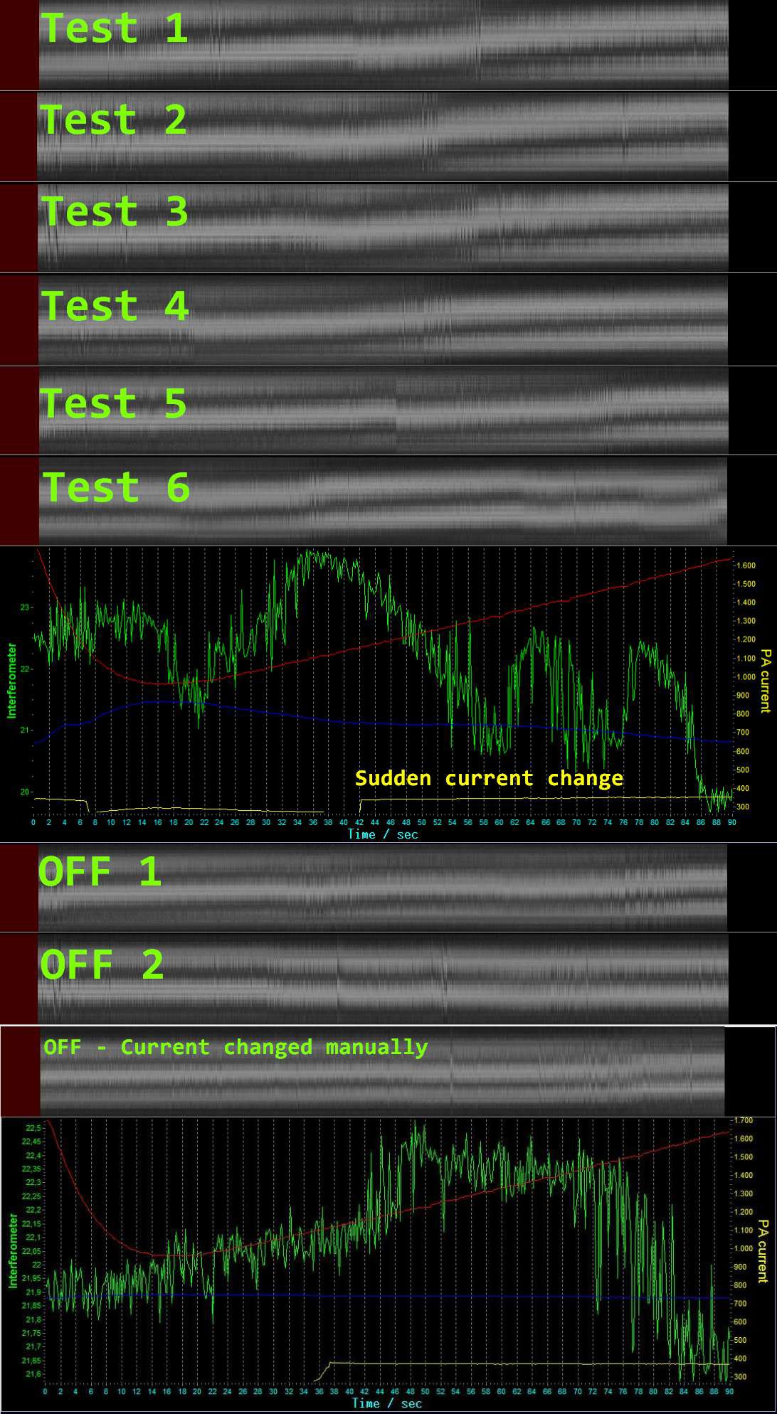
Playing arround with the setup. It turns out that there is a change in displacement around 25 GHz. That´s the upper end of our RF source, but several tests showed a change here. It´s all the same in six continuous tests.
There is a sudden change in the PA current before the displacement change occurs. The interferometer change looks sometimes like cheaply cut in with a paint program, but it´s not, this are the original recordings. There are sometimes jumps in the interferometer lines. The chart update frequency is 5 Hz while the camera frequency is about 30 Hz, maybe that´s also the reason that these jumps look so sudden.
I inserted some tests with the transmitter turned off, as you can see the displacement doesn´t occur in that situation.
One possible parasitic force which could cause a displacement could be the current flow to the system. In the last test I switched the transmitter off, but manually adjusted the current to make it look like in the previous tests.
But it did not show the displacement. So it seems that the current flow does not produce parasitic forces.
The interference pattern changes over time ( I assume it´s the temperature drop in the evening, so I need to adjust every few tests to get a reasonable pattern)
The experiment shows another implication of thrust - but we don´t shout it out yet ;)
We want first to know what you think about that. It´s the first test, so we don´t judge, we just play and watch.
I´ll take some time to make the software ready for you to browse and export the data. Please give me some time.
Discussions
Become a Hackaday.io Member
Create an account to leave a comment. Already have an account? Log In.
Could be change in S-N ratio.
I would put another accelerometer on there, just to give orientation information to see if there is a directional bias.
From reading the data on the higher power tests it seems that there is a "beam" of sorts aligned with the axis of the chamber, if that beam is aligning with something else then the chamber's orientation is much more critical than people first thought.
Also have you considered setting up a radiation detector at the "focus" to see if anything interesting shows up? I have seen evidence of possible X-radiation emission from porous vacuum encapsulated semiconductors in the literature so it would be worthwhile doing the experiment.
Are you sure? yes | no
There is a diffrence in the pattern from test 5 and the rest. The other test seem to have a more diffuse transition. Or am i wrong?
Are you sure? yes | no
Adding a randomizer might be a good idea so there is no direct control on just when the RF is energized.
This IIRC is good experimental technique known as "double blind"...
also re. pencil it might work but graphene would be better, getting an even coating would be a whole new level of pain (tm)
Are you sure? yes | no
Staying tuned indeed. Is it worth someone building a graphene coated silver (GCS) chamber to see if the thrust is higher or lower as I suspect it will be much higher due to graphene's increased ballistic electron conductivity and subsequent higher Q factor of the chamber.
Are you sure? yes | no
That would be great. First we need to find out if the force we are measuring really comes from the cavity. But it´s not easy to get an interference pattern which stays stable over a longer time.
My biggest problem now is not the vibration but the drift of the interference pattern. When it´s drifting, a force is not clearly visible.
Are you sure? yes | no
is there any chance you can trigger the pattern somehow to eleminate drift? (thas't the reason i mentioned a occiloscope in the other reply. With a occiloscope attached onto the DAC you can synchronise the DAC's own drift so you can eliminate any interference patterns in the result.
Are you sure? yes | no
Can you just use a pencil to draw all over the silver? :)
Are you sure? yes | no
Do you trigger the output of the generator with help of a occiloscope ?
In electronics its nececcary to record minute measurements. You can filter out lots of noise in your system..
Are you sure? yes | no
No, i got a feedback loop using the divider of 16*65536 on the transceiver chip. The oscillator is controlled by analog voltage which I generate by a DAC.
Are you sure? yes | no
What is the bit level of the DAC? 16 or 12?
Are you sure? yes | no
16 bit
Are you sure? yes | no
A cheap way to prevent vibrations (by yourself) is: wear fluffy bunny slippers. I know they work well, my GF sometimes sneaks in on me wearing those. If you can't hear it coming, theres no vibraton! :)
Are you sure? yes | no
I have sth like this, same construction just without bunny ears :-D They work ok, but the interferometer is so sensitive, it catches even them.
Are you sure? yes | no
maybe its usefull to move your experiment to a place with a concrete floor, a garage perhaps?
Are you sure? yes | no
Paul, see the thread on Reddit:
https://www.reddit.com/r/EmDrive/comments/3m094c/possible_thrust_and_positive_results_from/
People demand you post raw data as a CSV file, so they can process it and extract signals, if there are any.
Are you sure? yes | no
lol people demand
Are you sure? yes | no
Hehehe, I demand... more free time for projects, more money, sunny weather and beer
Are you sure? yes | no
lol sorry, English is not my primary language and "demand" for me just meant "ask". I verified and it is more like "command" hem ^^
Whatever Paul, I saw in your next post: "There will be also an export function for the data into a CSV text format."
So thanks.
Are you sure? yes | no
It looks very similar like a TV Burst signal to me..
Are you sure? yes | no
I promised to do that. I´ll take some time today and extend the software with an export function, so you can zoom into the area of interest and export data - just give me a little time :)
Are you sure? yes | no
Sorry to say this, but this report is very confusing and not helpful.
- no explanation what the colors mean
- no explanation what does it mean that the green line is not correlated to the power on signal
- no reported Q value or possible thrust report.
- no idea what displacement happened
- no report what direction the frustum was
- how did you convert interferometry data exactly?
- "PA current" what's PA?
- why did the current change?
My suggestion is to report things in smaller, but clear chunks. It's not a good message to say that "I'll just throw the data I recorded over time and do whatever you want with it". Please take some time, add more explanation what you did and create multiple charts where it's obvious what's going on, because currently it's just confusing.
Are you sure? yes | no
Watch the video and read the logs, then it will make sense. PA is the official abbreviation for power amplifier.
Are you sure? yes | no
I've seen it and it did not. As another feedback, it would be incredibly useful to hear your audio comments instead of 8bit music.
Are you sure? yes | no
@Tibor: The video is on YouTube:
(the telemetry curves begin at 2:05)
Those curves are explained in the previous post:
https://hackaday.io/project/5596-em-drive/log/25744-interferometer-first-tests
Are you sure? yes | no
Nice video, gives clear understanding of the setup. Have you considered using a filter or sheet of thin paper in place of your screen and placing your camera behind the screen? In addition to this you could also tilt the camera on it's side - this would maximize the image projection onto your camera's CMOS/CCD array and also the number of useful pixels in the vertical axis.
Are you sure? yes | no
Great job! I'm really excited to see more data!
Are you sure? yes | no
Awesome work - you are making amazing progress!
Addressing the interferometer jumps and aliasing effects, is it possible at this stage to implement a linear CCD or CMOS photodiode array such as: http://playground.arduino.cc/Main/TSL1402R or even: http://ams.com/kor/content/download/250183/975717/file/TSL1406R_Datasheet_EN_v1.pdf
This would give you a much much higher collection rate... though probably a lower pixel-to-displacement resolution (depending on what is physically possible with your setup)
Are you sure? yes | no
Yes, I planned to do that, but due to the limited time I had to go back to a camera. But the displacement seems to be only about half a wavelength, so fortunately this approch seems to be sufficient.
Are you sure? yes | no
Does the interferometer has its own separate power unit? This could be important, if you try to plug it in the mains, every lightswitch in the system or even a fridgepump will spoil the results. You might need a spike filter on the mains plug too to eleminate car sparkplug pops.
Are you sure? yes | no
This is a good point, how are you powering your apparatus? If possible each device should be powered via an isolated power source (e.g. batteries).
Are you sure? yes | no
The RF source is powered by batteries, the interferometer needs only power for the laser and the camera, so both are powered from USB of the control PC. The laser does not need a perfect power supply to stay coherent, and the interferometer is not sensitive to electrical interference, but very sensitive to vibrations instead. But vibrations can be damped very well compared to electrosmog which is literally everywhere.
Are you sure? yes | no
Are you using a laptop running on battery? There can be a lot of 60Hz noise (and harmonics) in USB if you are using a computer which is connected to mains.
Are you sure? yes | no
Nice work! Awesome start, looking forward to seeing more data. Those first 6 tests look very promising. Is the system hitting 25 GHz at the same time in each trace? Because the clear shift in displacement is slightly different for each of them. Also, what is the green trace exactly? I know you said it's a sum of interferometer pixels or something, I didn't follow that. I'll have to think about ways to make it less noisy.
I'm pretty sure the drift is because of temperature swings, things just cooling off overnight. Don't really know a good way around that, except figure out a way to do shorter tests. Barring of course temperature stabilizing the whole rig, which sounds like an insane task to get it accurate enough. Are you doing this in a basement? I know my basement is usually much more temperature stable than the rest of my house. Do you have the system covered to prevent air currents from the room? The other weird thing is that, in theory, pumping power into the system should make the air around it heat up somewhat, which could mess with the laser. Not sure how to eliminate that either. Do you have vacuum tests planned?
Nice work, good luck!
Are you sure? yes | no
The frequency sweep is the same for all tests, it hits at the same time.
The green trace is the pixel sum over a thick line, aligned on one interferometer ring, I´ll post a picture later.
This rig is too big for my vacuum chamber.
The system is covered. I did this test with the setup on the floor in a styrofoam box.
I thought that maybe the current through the system could be responsible for the thrust, so I made an OFF test, but adjusted the PA bias so the same current was flowing than in the ON tests at the same time (it´s the last test in the bottom of the picture)
Are you sure? yes | no
Staying tuned! Good work, sir
Are you sure? yes | no
Thanks
Are you sure? yes | no