The voltage to frequency conversion circuit is the following:
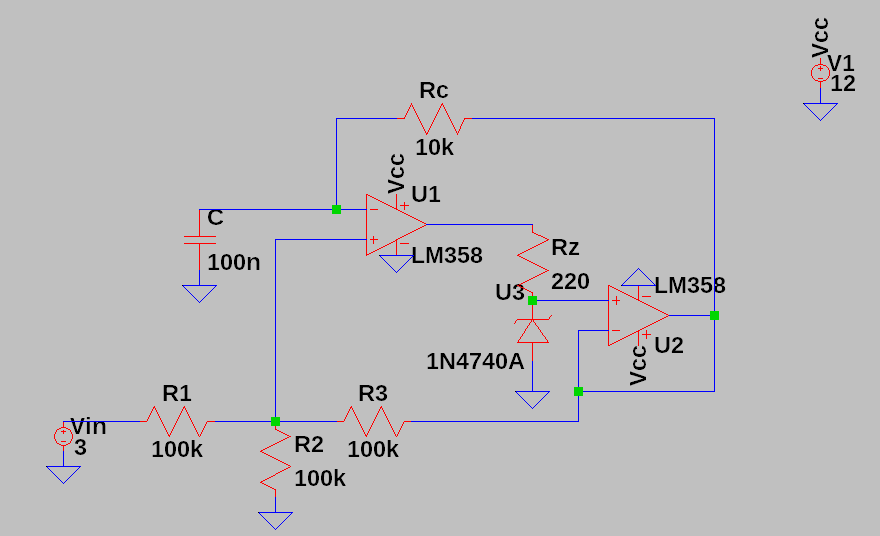
The zener diode has a zener voltage of 10V.
After calculating, the equation which describes the output oscillation frequency with relationship to the voltage Vin applied at the input, assuming Voutmax = 10V,of the circuit is:
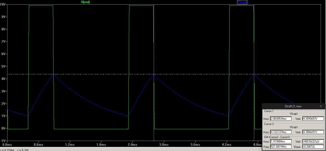
For the given values of Rc = 10k ; C = 100n and Vin = 3V, the calculated output frequency is 518 Hz while the simulated one is 521 Hz. Not bad, the errors are probably there because of the output resistance of the op-amp. I thought of a nice method to describe and eliminate that error in the case I don't find the output resistance of the LM358.
Discussions
Become a Hackaday.io Member
Create an account to leave a comment. Already have an account? Log In.