 RasmusB
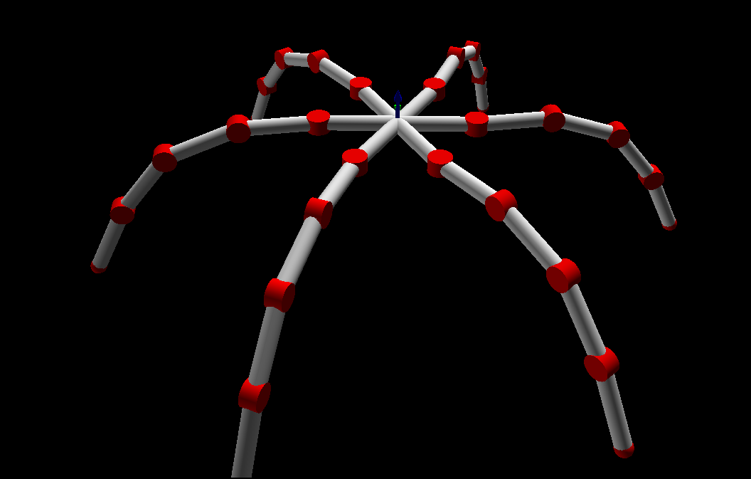
I have been thinking about this project for some time. It all began with a video on Youtube of a hexapod robot:
 At this point (fed up with programming) I decided that I should look into improving the servo controller usually found in a standard RC servo. Not because it was entirely necessary, but because it seemed fun. I found a few open-source alternatives, but they all ended up being unsuitable in one way or another. So I set out to build my own.
I decided that the servo should communicate through a CAN bus.
After a lot of experimentation and frustration with Arduino and a few MCP2515-based CAN shields, I decided that I should go for a microcontroller with a built-in CAN controller instead. The size requirements also dictated this - if it was going to fit inside a RC servo, I won't have room for both a microcontoller and a CAN controller. The choice fell on the ATmega16M1 - basically an ATmega328P with CAN and a dedicated motor controller, but half the amount of flash/RAM. If necessary, I can easily upgrade to the pin compatible ATmega32M1, or its big brother ATmega64M1.
This is my first prototype (the purple board) compared to the original servo controller. The next revision will have shrunken my design down to an even smaller footprint than the original.
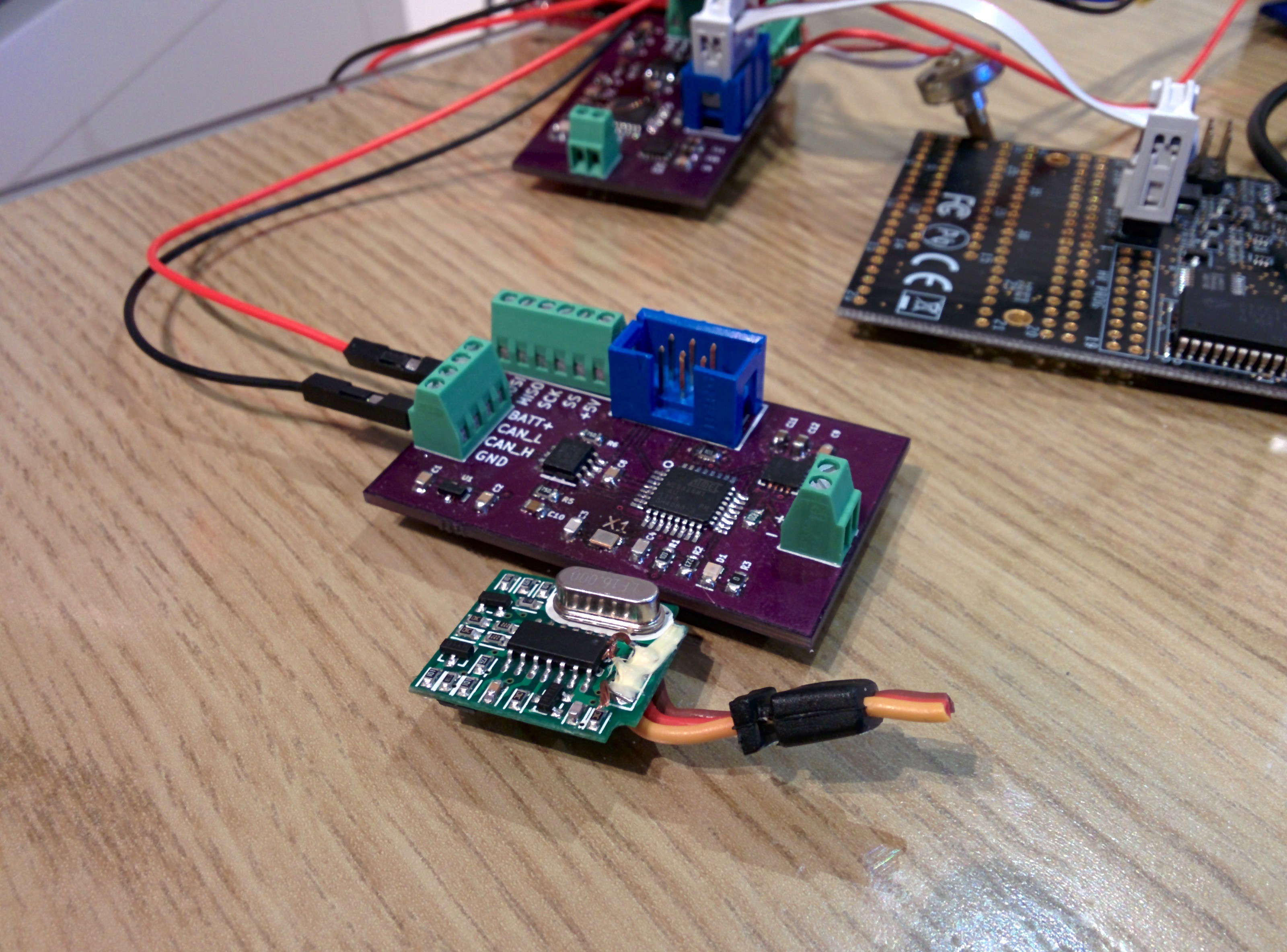 This prototype was build to to a basic concept test - especially of the CAN communication. After being completely fed up with trying to build some kind of USB - Arduino - MCP2515 - CAN adapter, I built CANPi.
Stay tuned!
Discussions
Become a Hackaday.io Member
Create an account to leave a comment. Already have an account? Log In.