 William
Maker Faire Bay Area 2015 and the events leading up to it really helped refine the specification in a few very important ways. First, I found many of the features packed into the DB-25 spec should be moved to DA-15. This was in an effort to make the spec more accessible as one gets started. The DA-15 spec is not the best candidate for a plethora of chained modules. If chainability is your main focus, shift over to DB-25 and/or DE-9.
The old version of the spec featured USB and lacked CAN. USB is difficult to support when chaining is considered. USB is also a riskier thing to mess around with, since it probably has an expensive computer connected to it. CAN, on the other hand, chains easily and can be run over long distances. It is not as fast, but is sufficient for many electronics experiments. It is used extensively in automotive, automation & robotics environments.
Finally, after taking a look at some other multi-pin connectors, I found it wouldn't be to difficult to support 1080i HD video. While not the cleanest means of transmitting video, it is an ideal transmission method for those who like to tinker. The other connectors I mentiond combined composite, 'super' video & component video onto three pins. This pattern has been followed with the DB-25 connector pin spec.
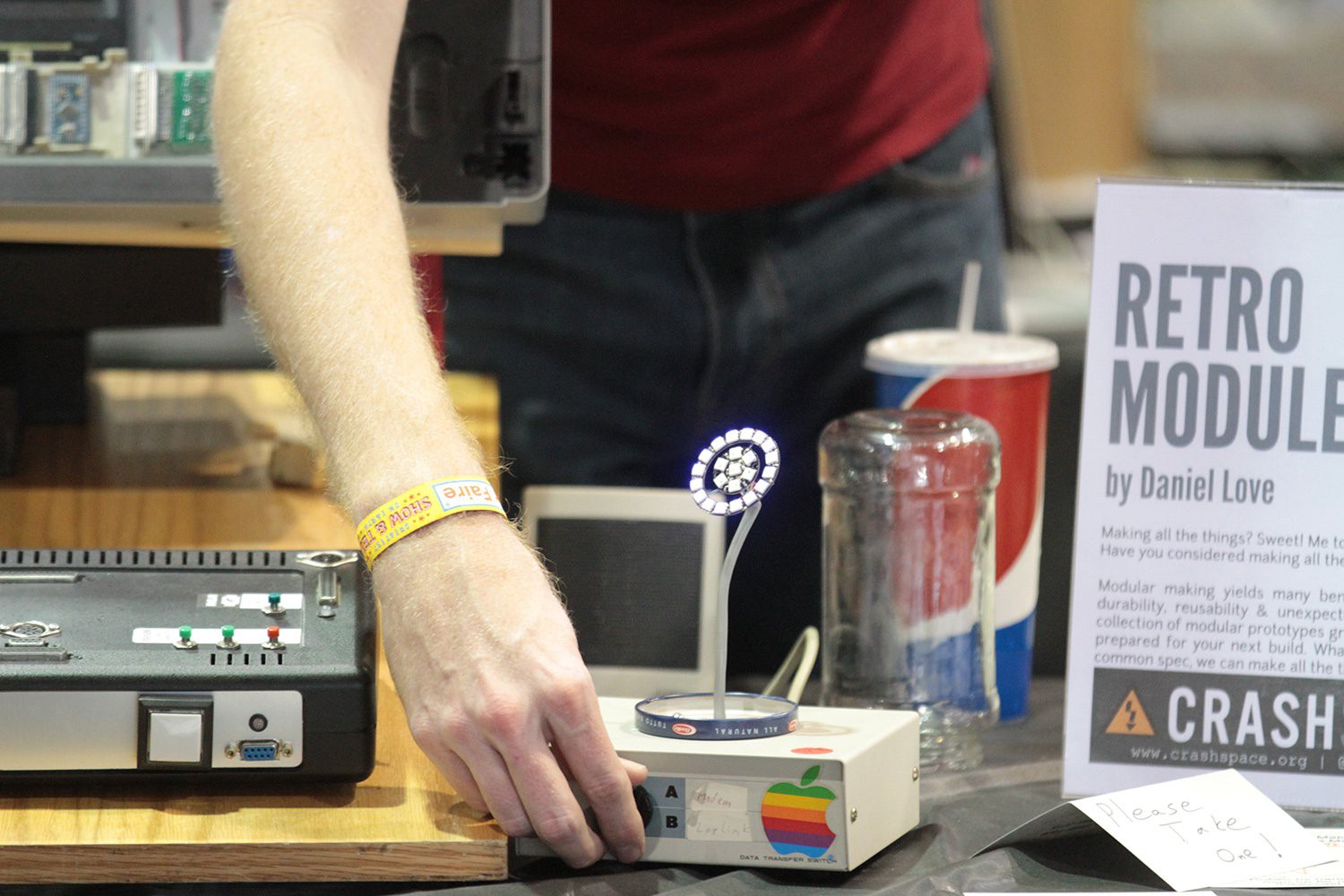
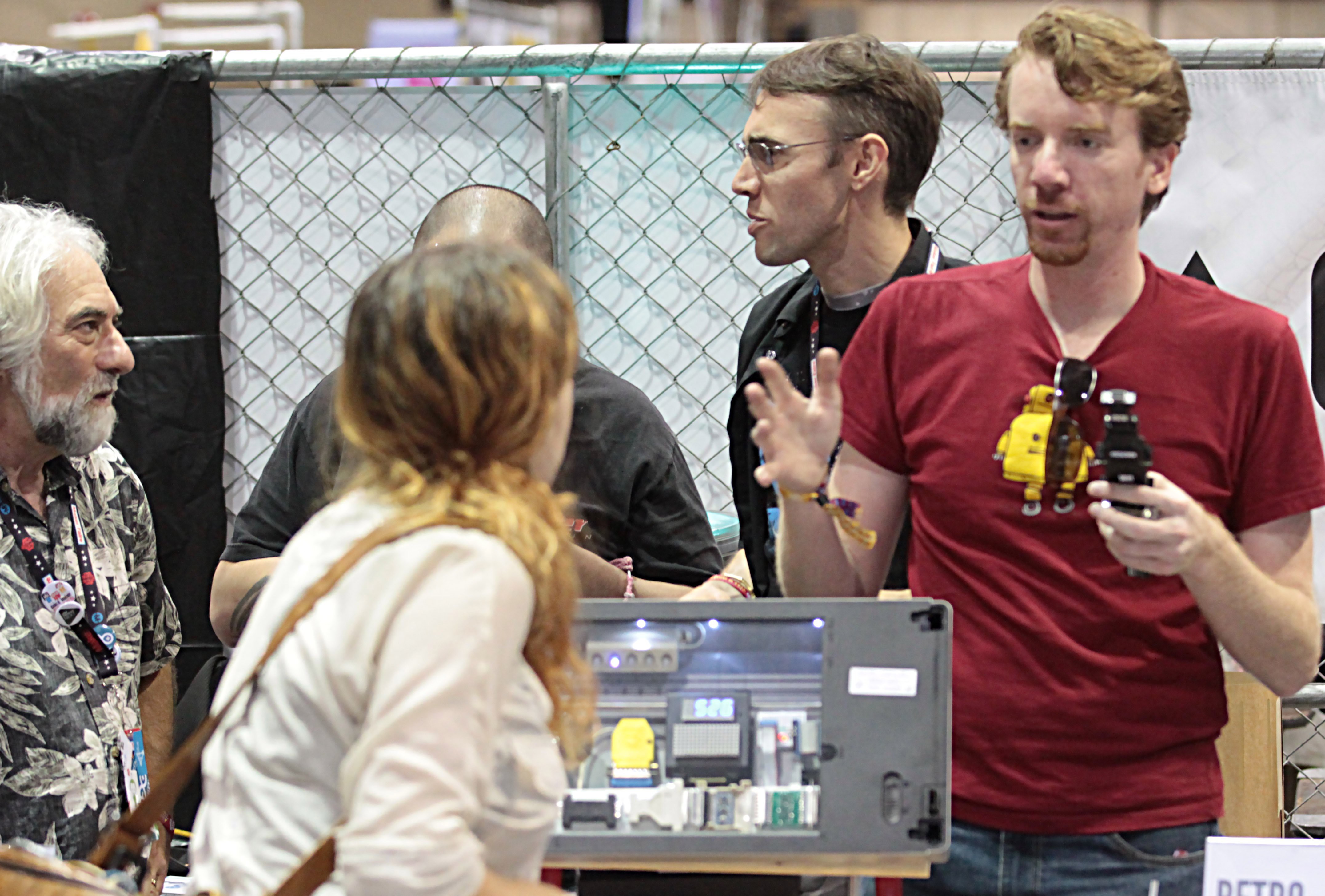 When I decided to make an appearance at Maker Faire, I knew I would need a set of modules to help attract interest. I chose to embed a number of modules into an old flatbed scanner -- along with an Arduino Uno to run everything. The control surface featured all sorts of buttons & fiber-optic-backlit DE-9 & DB-25 connectors. The buttons & LEDs were driven by I2C port expanders & the NeoPixels via the `pixel-bus`. When one (or a few) of the buttons were pressed, the pin holes corresponding to the button label(s) would illuminate. Since I already had a 16x8 I2C LED display, I programmed the Arduino to display button label text there as well. The LED display was behind the scanner glass, while the control surface was mounted on a board well below. The scanner 'display case' and other parts of the display were linked by a single 25 connector ribbon cable. There were other means of input & output as well. Important to the design: I needed certain modules to protected, while others could be messed with. Those goals were well achieved.
Discussions
Become a Hackaday.io Member
Create an account to leave a comment. Already have an account? Log In.