 Jon Davies "Woody"
This was in fact the first bit of research I did when setting out on this project, back even before I had bought the Nixie Tubes. At this point, I had been putting various items in the online shopping basket (including the Nixies) and had a suspicion that I'd need to control the Nixies from something that could interface logic 3.3/5v with the 170v required by the Nixies. This was the point at which I came across the K155ID1 Nixie Driver IC, and a suggested operating circuit:
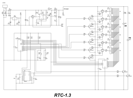
I filled out the rest of my order based pretty much solely on this schematic, plus a few extras and minor modifications. I also got the HV Module as a result of simply asking an online agent where on earth the 170 volts was magically appearing from.
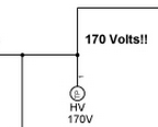
You don't ask, you don't get. Well, sort of - I still had to pay for the HV Module - free would have been nicer ;)
Looking at the diagram above, I can see that the K155ID connects to all the Nixie Cathodes on a bus, and each of the Anodes are switched by the PIC Micro-controller, meaning the K155ID is multiplexed. The benefits of this is that you only need one Nixie driver chip, and the circuit is less complicated. The disadvantages are [potentially] noise and flicker caused by the multiplexing.
I'm opting for multiplexing for now and will see how the results pan out.
Discussions
Become a Hackaday.io Member
Create an account to leave a comment. Already have an account? Log In.