 peter jansen
A quick update with nearly-complete mechanical progress (!), including creating the table, and the radiation shield used for calibrating the detectors. The focus here has been on having the unit completely self-contained, so it can do long calibration procedures (featured in the next post), and of course scanning procedures.
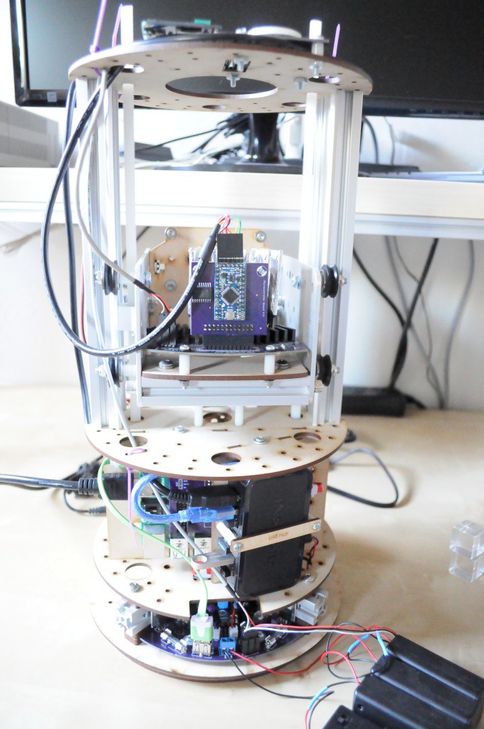
The (nearly complete) unit, on the workbench. Though it looks very similar to the last revision, nearly every piece has been modified with mechanical considerations for cabling, assembly, and having the entire unit self contained within an 8-inch cylinder (so that a case can be designed to slide over it, and look attractive on one's desk).
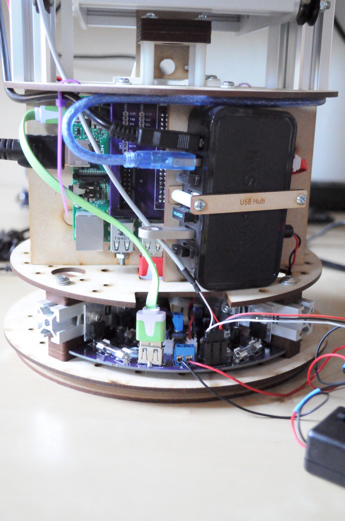
Here, the cables for the two Arduinos (one on the imaging array, the other to control the linear and rotational stages) are finally securely mounted and plugged into the USB hub. The remaining positions in the hub include:
- A 16GB USB flash drive, which hosts the Raspberry Pi filesystem. This is used in lieu of the traditional SD card in that it's both faster, and seemingly much more resistant to being corrupted.
- A Wifi module, for headless operation. Much of the software that I've been writing has been developed on the machine itself, using a remote desktop over VNC.
- USB Keyboard and Mouse
The HDMI connection to the Raspberry Pi is also visible on the left. One of the final mechanical considerations is to laser cut a plate for the back of the machine that breaks out the HDMI, one USB, and the power connector, and to find short panel-mount extension tables for these ports.
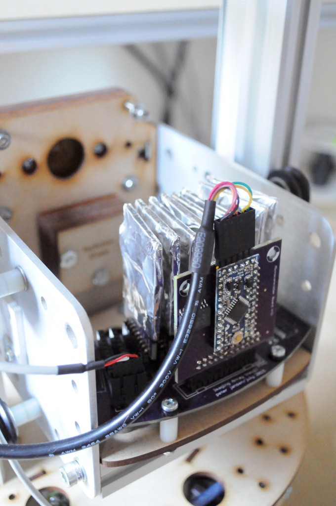
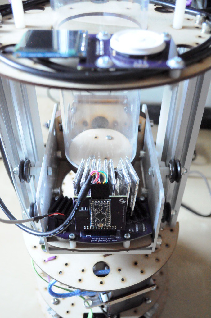
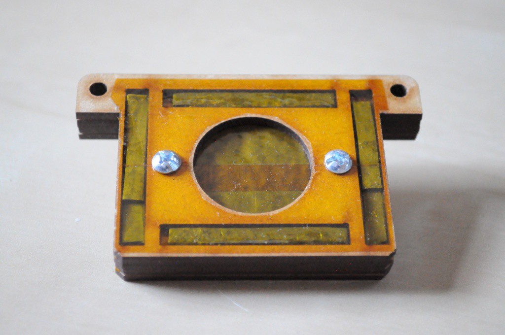
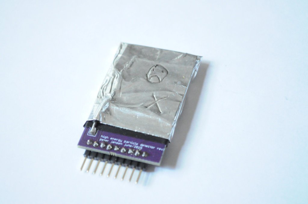
Because the development environment is notoriously hostile to parts, I'd populated the imaging array with only two detectors for testing, so that if something accidentally bridged, at worst only two of the detectors would be damaged. While the detectors have been designed to have a low bill of materials, they do take a fair amount of time to assemble, and time has been less available lately than I'd like it to be.
Here, I've populated 8 of the detector slots, for the calibration runs that I've been performing (more on this in the next post!)
Radiation Shield
In this picture, while the source isn't inserted, just below the aperture for the source, a difficult-to-photograph block with the writing "Radiation Shield" is visible. This shield is essentially a large amount of lead encased in some structure that place it directly in between the source and detectors, when the Z axis is in it's lower-most (i.e. parked) position. This is a critical part of the system design, and will allow the noise level of each detector to be calibrated automatically, both with and without being exposed to the source.
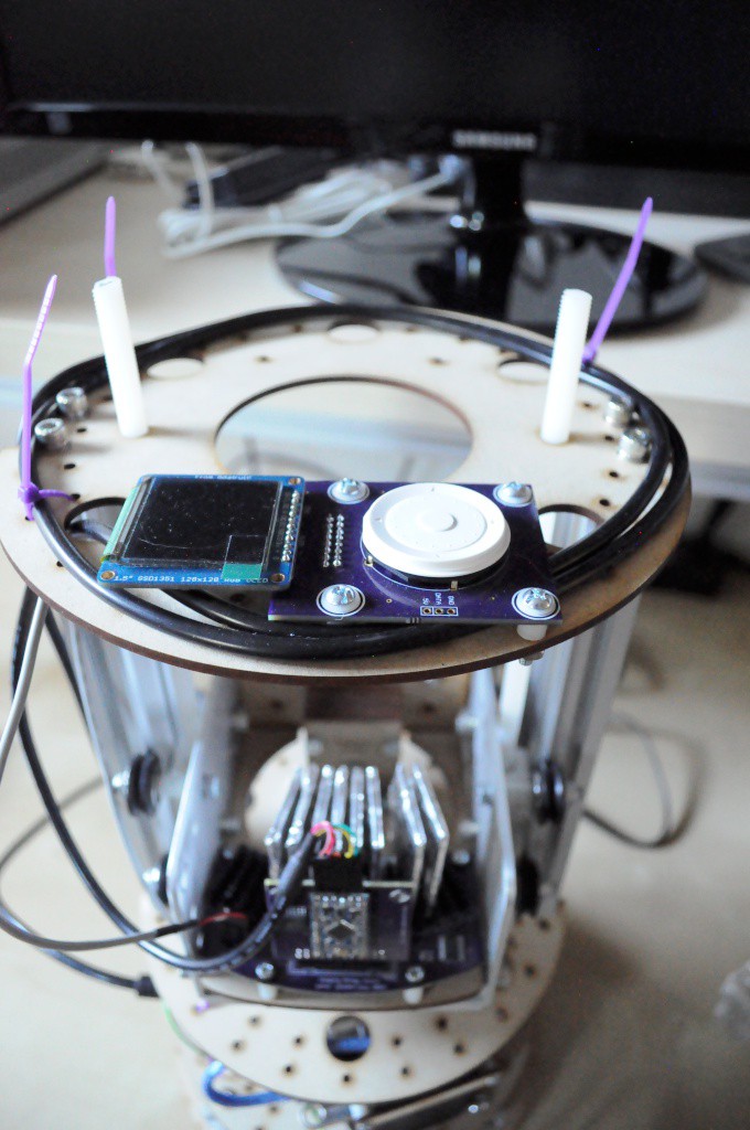
Status Display
The top of the instrument contains the control panel, that includes an OLED status display, and wheel-based directional pad. I very much like this controller, and have the software working with the Pi, and it's one of my favorite usability features of the machine. Keeping with my mantra of making this machine as easy to reproduce with as low a skill barrier to entry as possible, I've designed this with largely off-the-shelf parts, so it should be easily reusable by other folks for different projects, with a minimum of assembly effort.
Unfortunately using this display currently increases the noise level on the detector array by a factor of about three -- likely due to what looks like a ~13V boost circuit on the breakout board for the OLED, in spite of it already being reasonably isolated from the sensitive circuitry. This requires a bit of thought, so it'll likely be a little while before the status display is in regular operation.
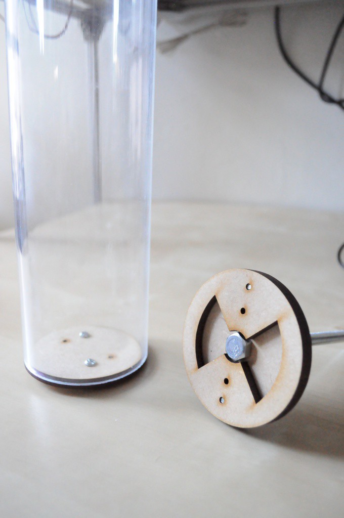
Keyed Table and Interlocking Sample Container
I've made a first prototype of a keyed, interlocking table, that allows the sample container to be easily and securely roated, while also being relatively easy to insert and remove. This is a good first-pass, but it's still a little challenging to find the right spot for the key, so this likely needs a second revision, with some thoughts on beveling the edges of the keys to allow a bit of wiggle room.
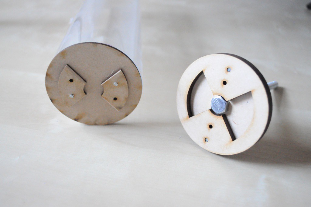
Above is another view of the keyed table (right), with the bottom of the sample container (left) and it's mating key pattern visible.

Above, the table can be seen installed in the machine, where a long bolt is used to transfer rotational motion from the center NEMA17 stepper, below.
And similarly, here the sample container has been placed above and mated to the table -- it rotates quite well. There is a tiny bit of slop, but given the low resolution of the scanner, this likely won't be an issue.

Above is the machine rotated 180 degrees, viewed from the source side.
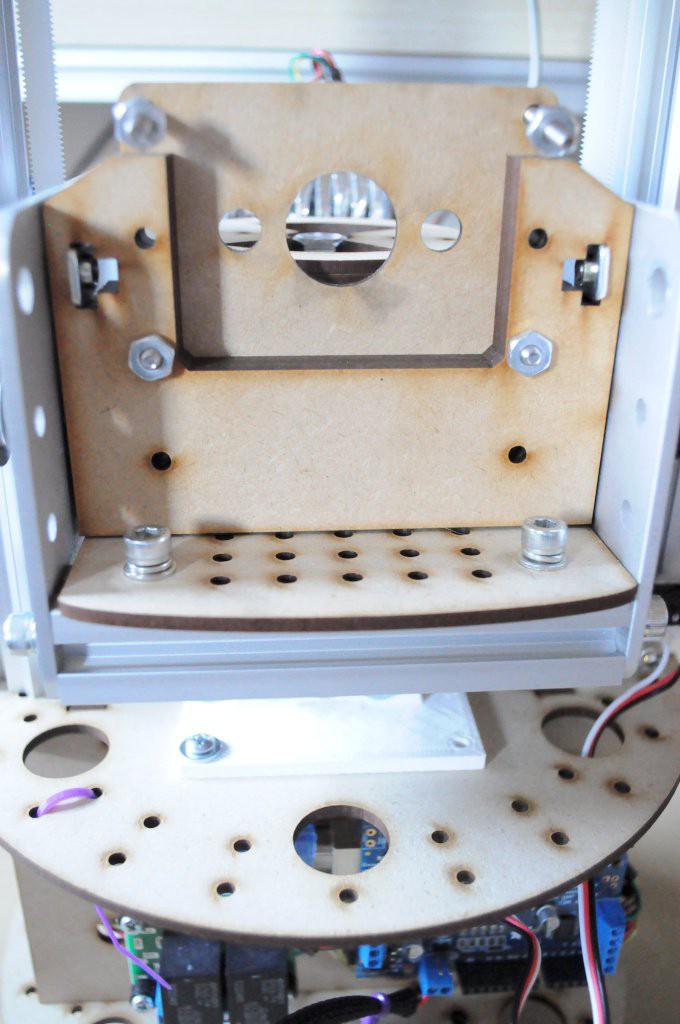
Here, the source holder has been removed, and can be seen below. The white 3D printed bracket seen mounted to the midplate serves as a mount point for the new source shield (that's used for calibration).
The Barium 133 radioisotope source fits snugly the source holder. Aside from it's mechanical job of holding the source in place, the layers of ~1mm lead sheeting substantially reduce the source intensity in the direction away from the detectors. It's clearly still a little leaky in some directions (most notably, on the sides, directly perpendicular to the detectors), so some work is still required here.

Above is the Arduino Uno and Motor Shield used to control the steppers. Most of the cabling is complete here, and now includes the cable for the Z limit switches. The relay breakout to automatically enable/disable the 40V photodiode bias source for the imaging array still hasn't been connected yet, but it's one of the few remaining items here, along with a magnetic reed switch for detecting table rotation.

The top limit switch, above.

And the bottom limit switch. Both limit switches are connected to the motor shield using a single 3-conductor cable (originally a servo extension cable), and the firmware has been modified to support these, including automatic homing and limiting over travel -- so the Z stage shouldn't crash into anything.
Calibration Runs
Most importantly, the project has progressed from being only an imaging array, to including a (nearly-complete) tomographic imaging mechanical platform with the supporting computational bits to cleanly, easily couple the imaging and motion systems together in a self-contained, desktop system. And with some effort taken to isolation and some of the design decisions, the imaging array is remarkably noise free (!).
The result of this is that the system has done a number of multi-hour long calibration runs to determine the optimal digipot values for each detector, with software developed and written on the scanner itself, and seems to be performing without many surprises. It's exciting to be so close, and to be near a place where I'm comfortable leaving the scanner to collect data for real scans over the period of many hours.
Thanks for reading, and stay tuned!
Discussions
Become a Hackaday.io Member
Create an account to leave a comment. Already have an account? Log In.
well done and congrats for making it to calibration
Are you sure? yes | no