If we want to know how much we have cleaned up our power supply, first we need to know how dirty it was in the first place. I'd like to take an FFT with my oscilloscope, a Rigol DS1052E (of course). I don't want to hook my probe up directly to mains, because I rather like living.
To step down the voltage, I've taken a regular wall-wart with transformer. This particular one was an ac to dc transformer, so I sawed it open and removed the rectifier and filtering caps. Then I closed it back up again and measured the output voltage. 230VAC to 8.4 VAC, so it has a turns ratio of 230:8.4 = 27.38, when terminated with a 10k resistor.
Then I opened it up again, and soldered wires to the primary of the transformer. Of course without it being connected to mains.
A transformer is a complicated device, with series resistance, inductance, and capacitances. But I'm expecting it to behave as a low pass filter up to a certain frequency, then resonate, and then act like a high pass filter. Hopefully the frequency transfer function up to at least 150 KHz is flat (no dampening or amplification of the voltage), because I'm interested in measuring the power line frequencies up to 150 KHz.
To test the flatness of the frequency transfer function, I've connected a signal generator to the primary (using the maximum output voltage and low impedance drive output), and for each frequency measured the Vrms (root mean square voltage) on both the primary and secondary.
Then I divided the primary by the secondary voltage, to get the ratio.
I then normalised the ratio so that the voltage at 50 Hz would be '1'.
Then I took the 10*log10(ratio) to get the amplification expressed in power. That leaves us with a traditional transfer function, although expressed in 10*log10(ratio) (power) instead of 20*log10(ratio) voltage amplification. I'm doing that because that's how the oscilloscope also spits out FFT spectrum.
Here are the results:

Between up to approximately 70 KHz, the voltage ratio is within 20% of the voltage at 50 Hz (the line frequency). Then it starts dropping off up to 200 KHz, and then starts increasing again up to 500 KHz.
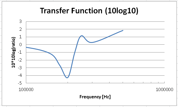
It looks like this transformer is resonating at 200 KHz. Resonance is the point where the inductive behaviour (resulting in the low pass behaviour) changes for capacitive behaviour (resulting in high pass behaviour). So at resonance these two components are equal.
What have we learnt?
This transformer is not perfect but suitable for measuring voltages up to 200 KHz. We know with what ratios to multiply the FFT in order to get a correct power spectrum when measuring with this transformer.
Discussions
Become a Hackaday.io Member
Create an account to leave a comment. Already have an account? Log In.