 Eric Hertz
Update: Adding before-and-after images of it in-circuit.
I still want to breadboard with this, but the bare-minimum, alone, creates quite a rat's nest, at least the way I breadboard...
Originally I planned on placing a PCB flat atop the chip... @antti.lukats's design for DIPSY, with its upright pins, was definitely a contributing-factor in this layout idea... But I had some difficulty figuring out how to do that with through-hole parts like the header-pins... and staring at it for a while, it finally came to me!
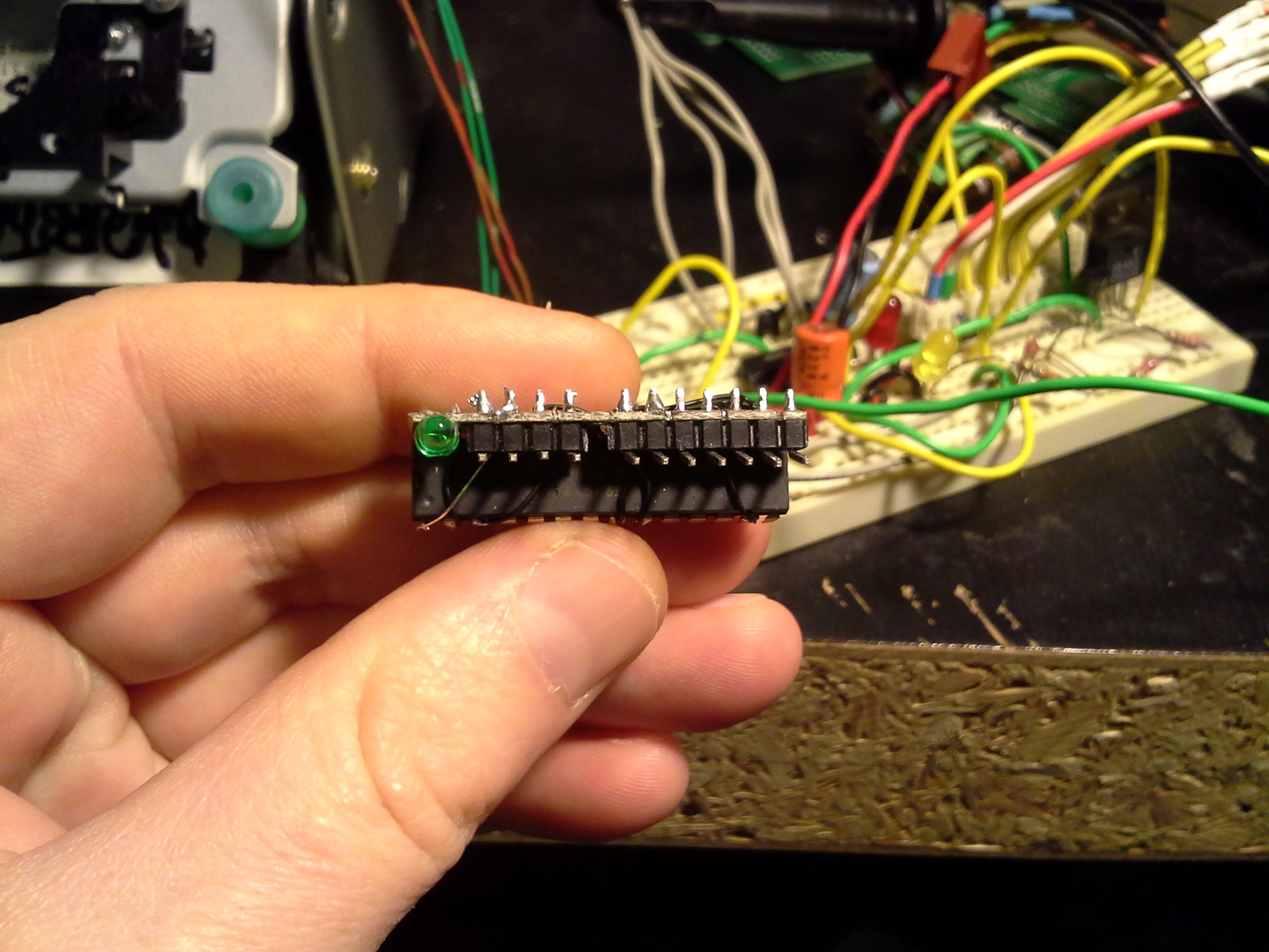
(Next time I'll use actual right-angle headers, instead of bending straight ones).
This is actually handy-enough I might do it with through-hole AVRs, etc. as well... So I'm thinking with my next custom PCB-run I'll include something like... what're those things called, not J-lead, right? Anyways, holes at the edge that are only half-circles, so they sit right atop a DIP's pins, where they enter its package. In this case, I just blobbed a ton of solder through the lowest row of holes until the blob finally reached the pins' faces. (The pins come out at a slight angle, so the PCB and its holes aren't actually resting flush on them).
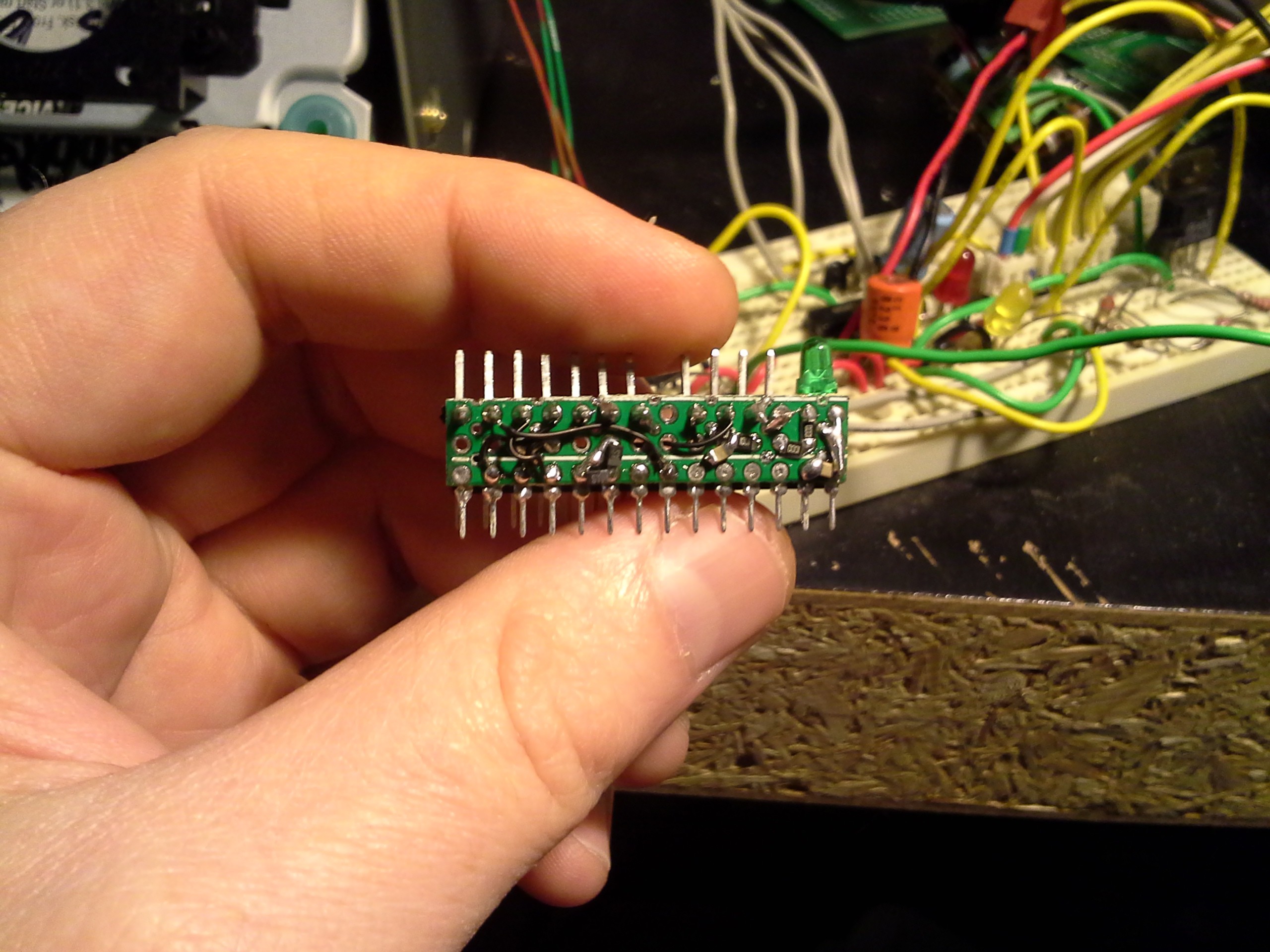
Most of the support-circuitry is connected to one side, but some wires needed to cross-over.
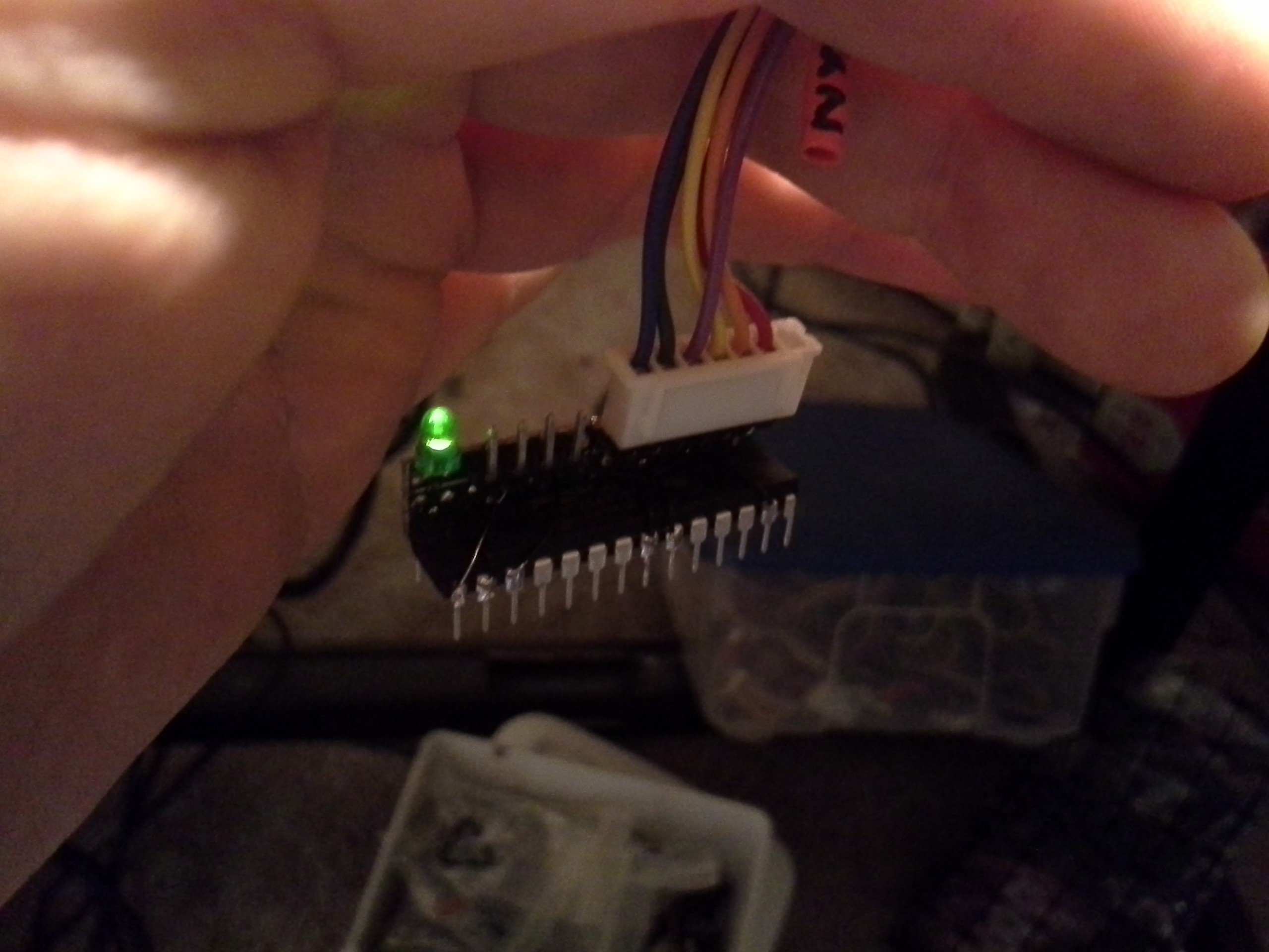
Everything needed to run code is now "on-chip"... The heartbeat is fading in this image, and it's also outputting serial data (and responding to received data) on the unpopulated serial-header pins.
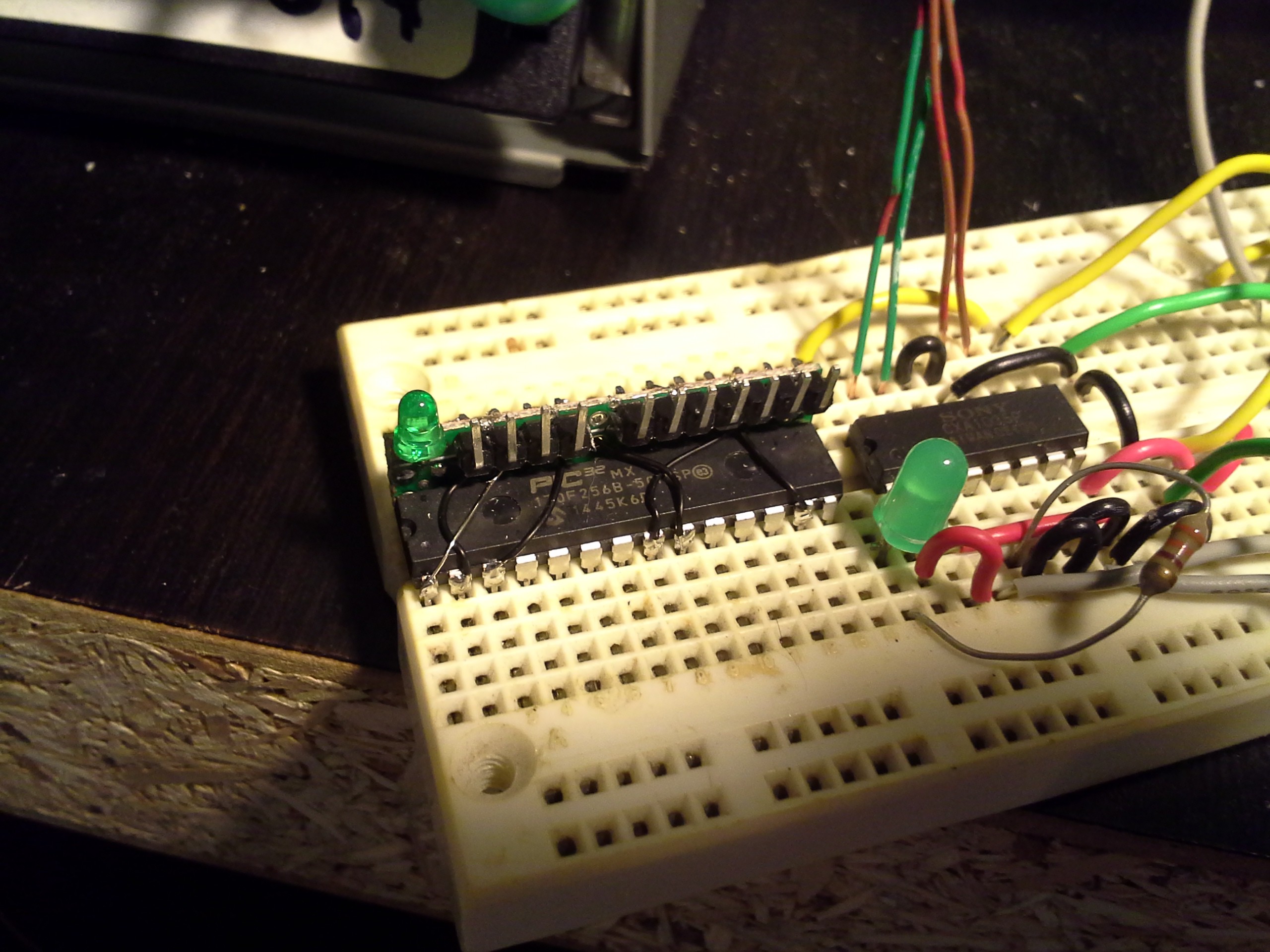
And it still fits in the breadboard without occupying (almost) any additional breadboard space, and should probably still fit in "machine-pin" sockets. In fact, it should work fine in a circuit designed for this chip, e.g. on a PCB with the same support-circuitry on-board.
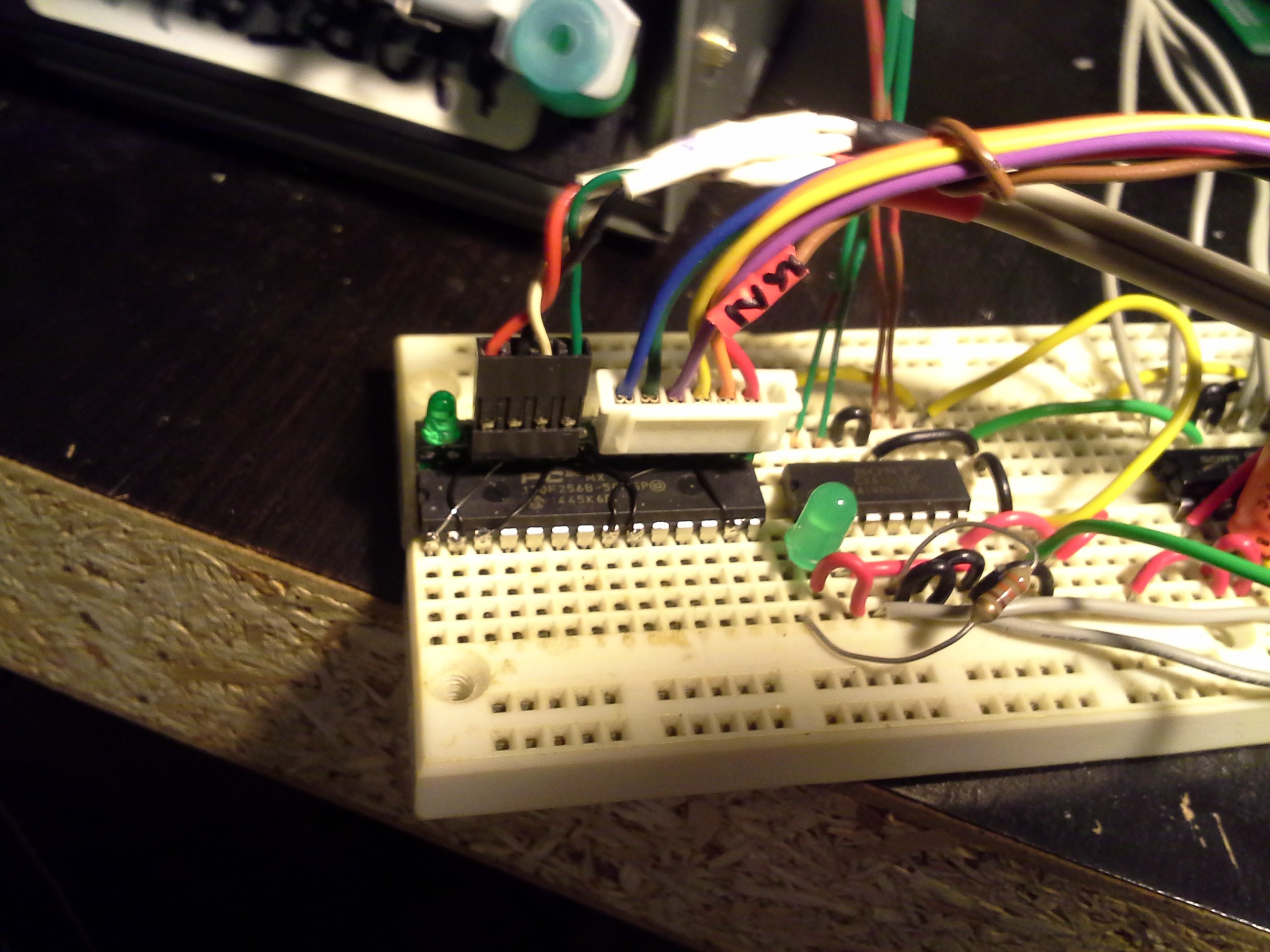
The left connector is for (TTL-level RS-232) serial I/O. The right is JTAG.
The other nice thing about the upright PCB, rather'n a flat one, is that the chip's part-number is still visible. Handy since I've got two in this family with slightly different pinouts/functionality.
That piece of red-heatshrink says NYI and covers the currently unconnected/unhoused 7th pin... That's for SRST or TRST, should I ever find a use for it. Though, I'm almost certain I've read somewhere that neither are necessary (nor even implemented?) for PIC32 JTAGging... (I shoulda bookmarked that and posted it as a response in the earlier logs regarding the various JTAG resets...).
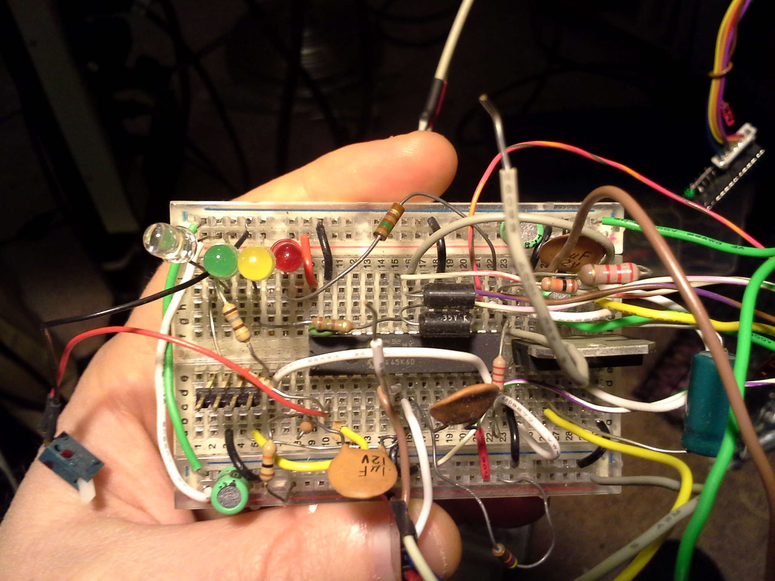
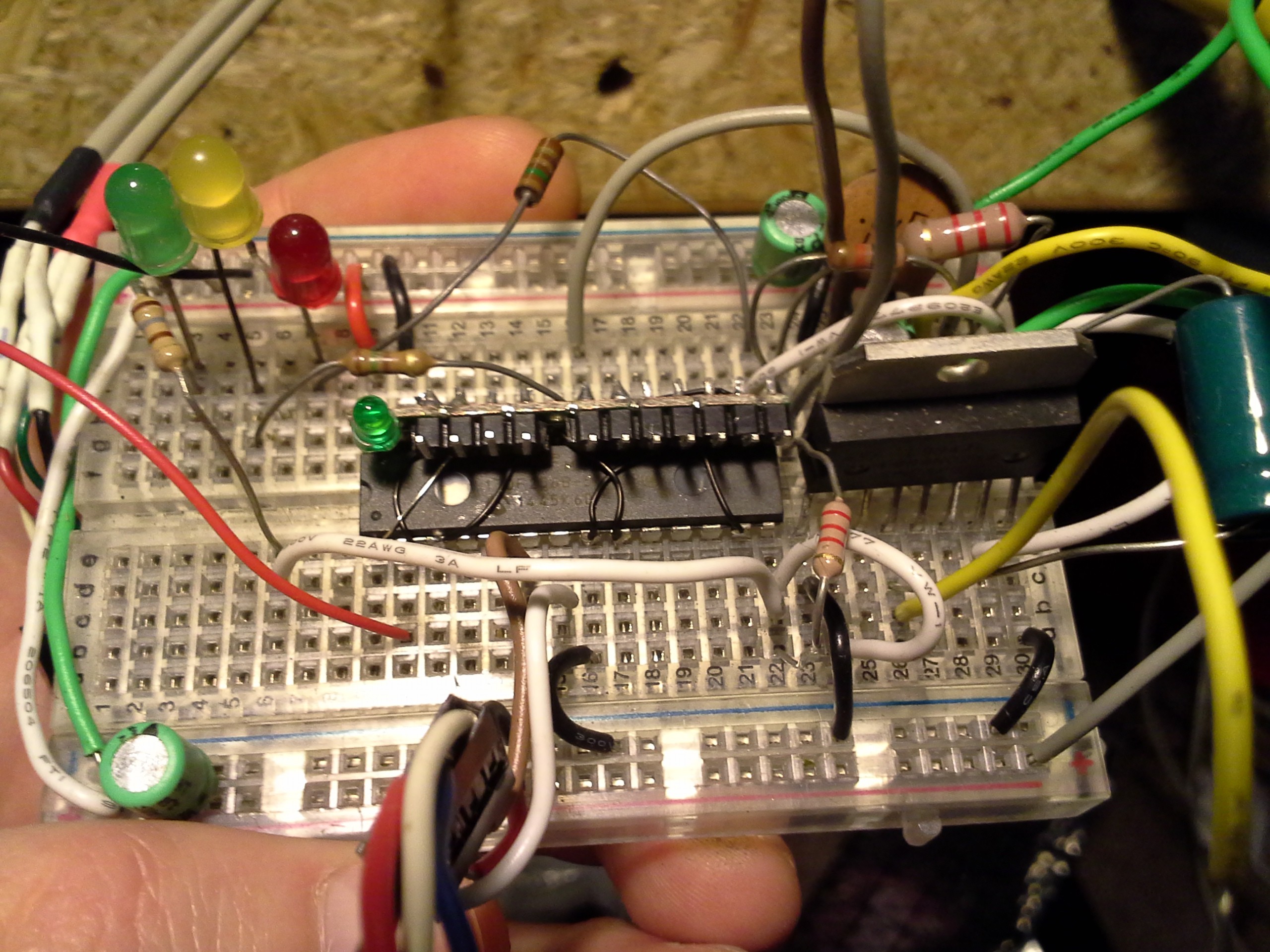
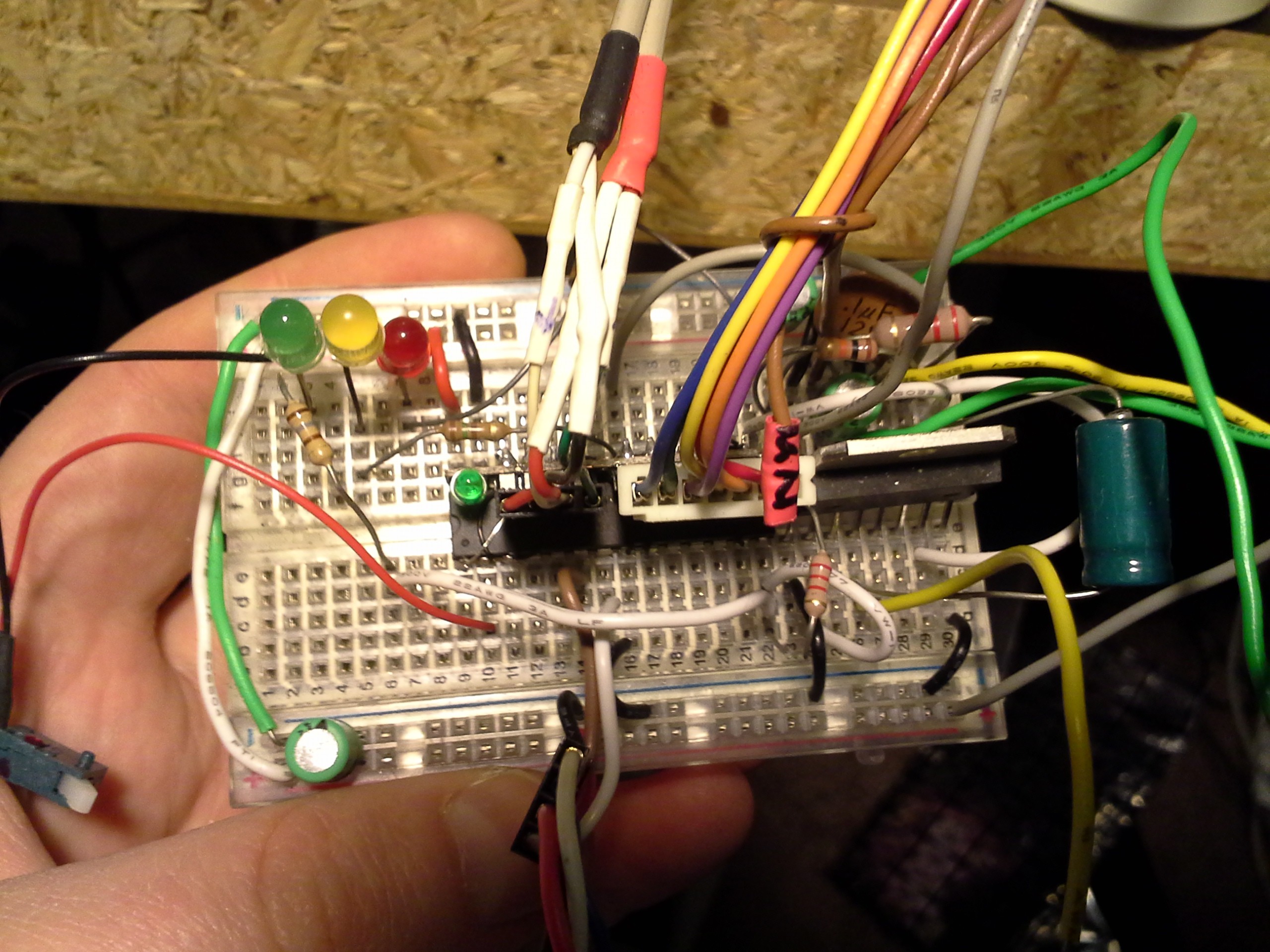
Here's a "before and after" of my motor-driver project:
Oh, and... starting to get the hang of this FT2232H breakout-board I've been using... Now making use of its second "channel" for the serial-port (and broke out pins for AVR programming, as well).
Discussions
Become a Hackaday.io Member
Create an account to leave a comment. Already have an account? Log In.